System and method for sensing loads

a technology of sensing load and system, applied in the direction of force measurement by measuring optical property variation, instruments, pedestrian/occupant safety arrangement, etc., can solve the problems of expensive apparatus and complicated, and achieve the effect of suitable calibration of system and easy access to information about person's weight and position

Inactive Publication Date: 2008-09-25
CARR & FERRELL
View PDF8 Cites 21 Cited by
  • Summary
  • Abstract
  • Description
  • Claims
  • Application Information

AI Technical Summary

Benefits of technology

[0013]Deformation of an optical fiber can be detected by measuring the attenuation of light passing through the fiber under the influence of the deforming force, such as pressure. This makes a useful weight detection system, as will be further described below. The attenuation can be converted to a weight value corresponding to a mass or force acting on the fiber. By providing a series of fibers in physically distinct positions, information about weight in different locations can be obtained, which provides information about the distribution of weight over an area of interest, thereby providing useful information about the weight and position of, for example, a passenger.
[0014]The basic form of the sensing system includes an optical fiber positioned relative to one or more supporting resistance elements such that when a force acts on the optical fiber to deform the fiber relative to a resistance element, light passing through the fiber will be attenuated. The degree of attenuation provides useful information about the amount of weight acting on the fiber. By designing a suitable environment for the fiber, its support, and defining how forces can act on the fiber, and by suitable calibration of the system, useful information about impinging forces is readily available. In a preferred embodiment, a mat containing a number of fibers is positioned under a seat cushion so that a person sitting in the seat will deform the fibers in the mat so that information about the person's weight and position can be readily obtained.

Problems solved by technology

Such systems provide highly precise measurements, but the apparatus is expensive and somewhat complicated.

Method used


Image

  • System and method for sensing loads
  • System and method for sensing loads
  • System and method for sensing loads

Examples


Embodiment Construction

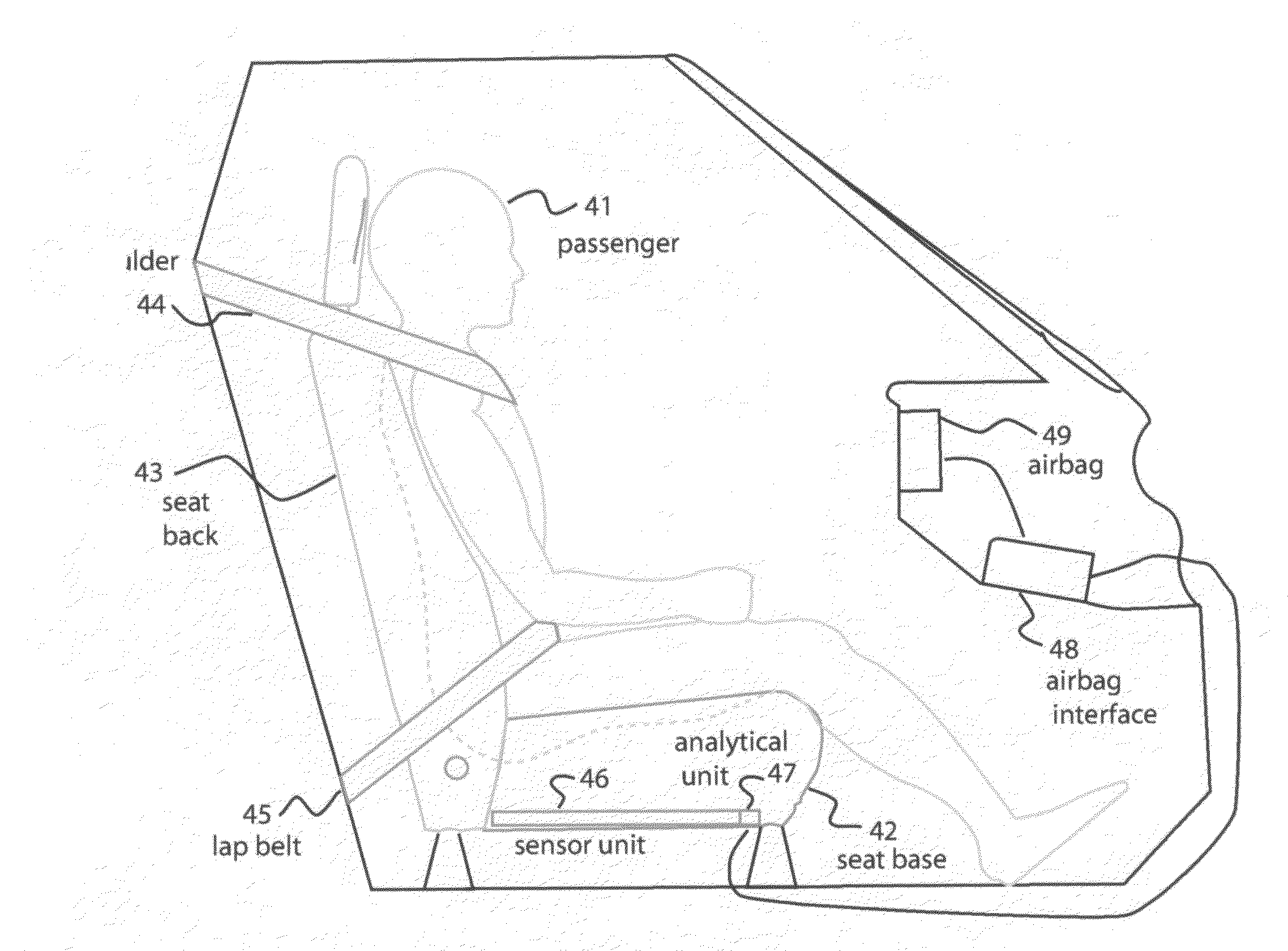
[0039]The present invention includes an apparatus and method for sensing the presence and weight of loads. In one specific embodiment, the invention may be used to determine occupant weight and the distribution of this weight in an automobile seat, to assist an airbag deployment system in selecting appropriate deployment of the airbag, i.e., with no, low, medium or full response, depending upon comparison of this data to a range of possibilities. In a typical installation, a side airbag and front airbag are individually positioned and controlled, although there may be some degree of integration of the sensors or activation devices connected with deployment. A simple sensing system of one embodiment of the invention can provide data suitable for input to airbag control or computer systems. Such a system can differentiate positions and weights, distinguishing an infant or child from a small adult or normal sized adult.

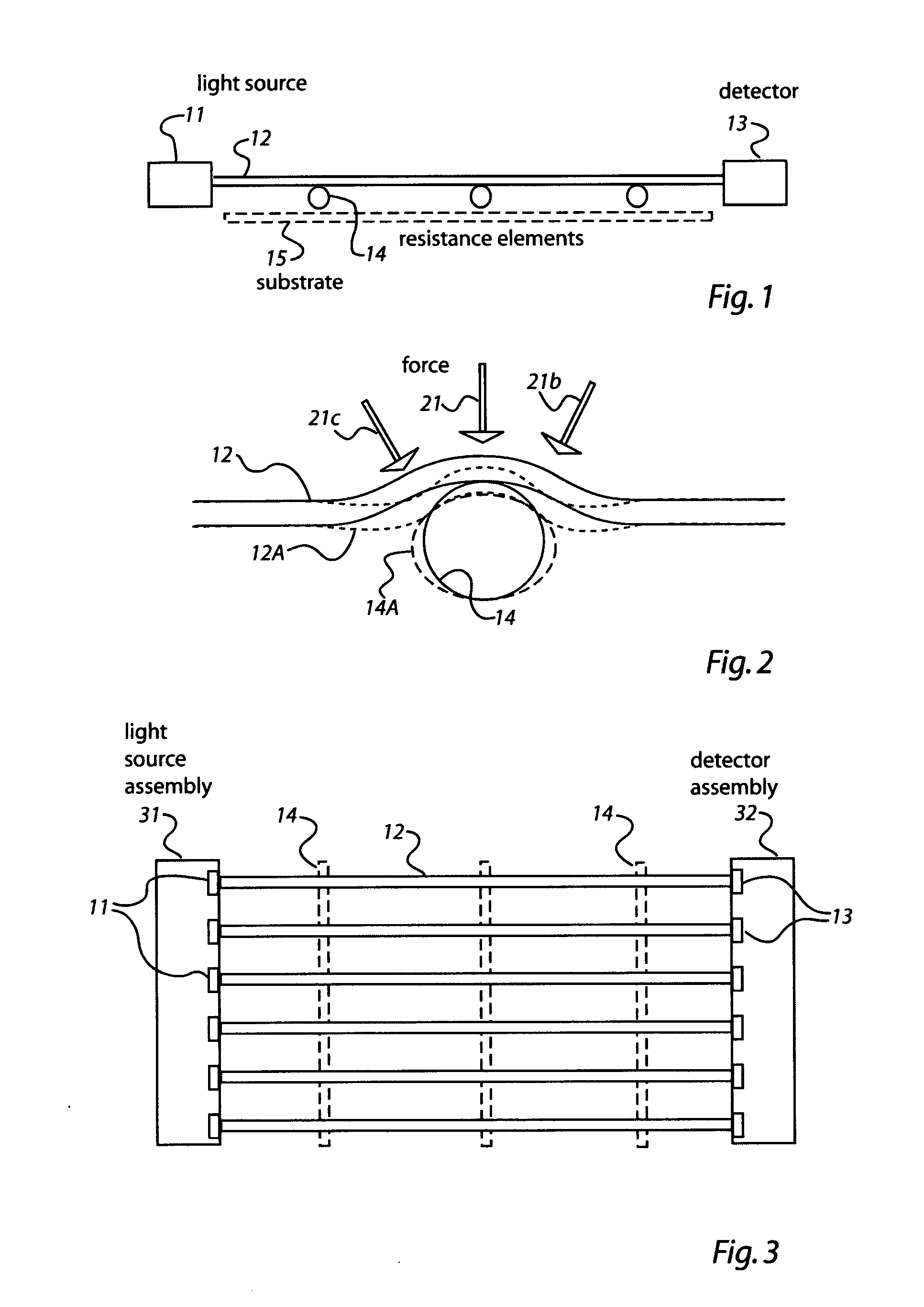
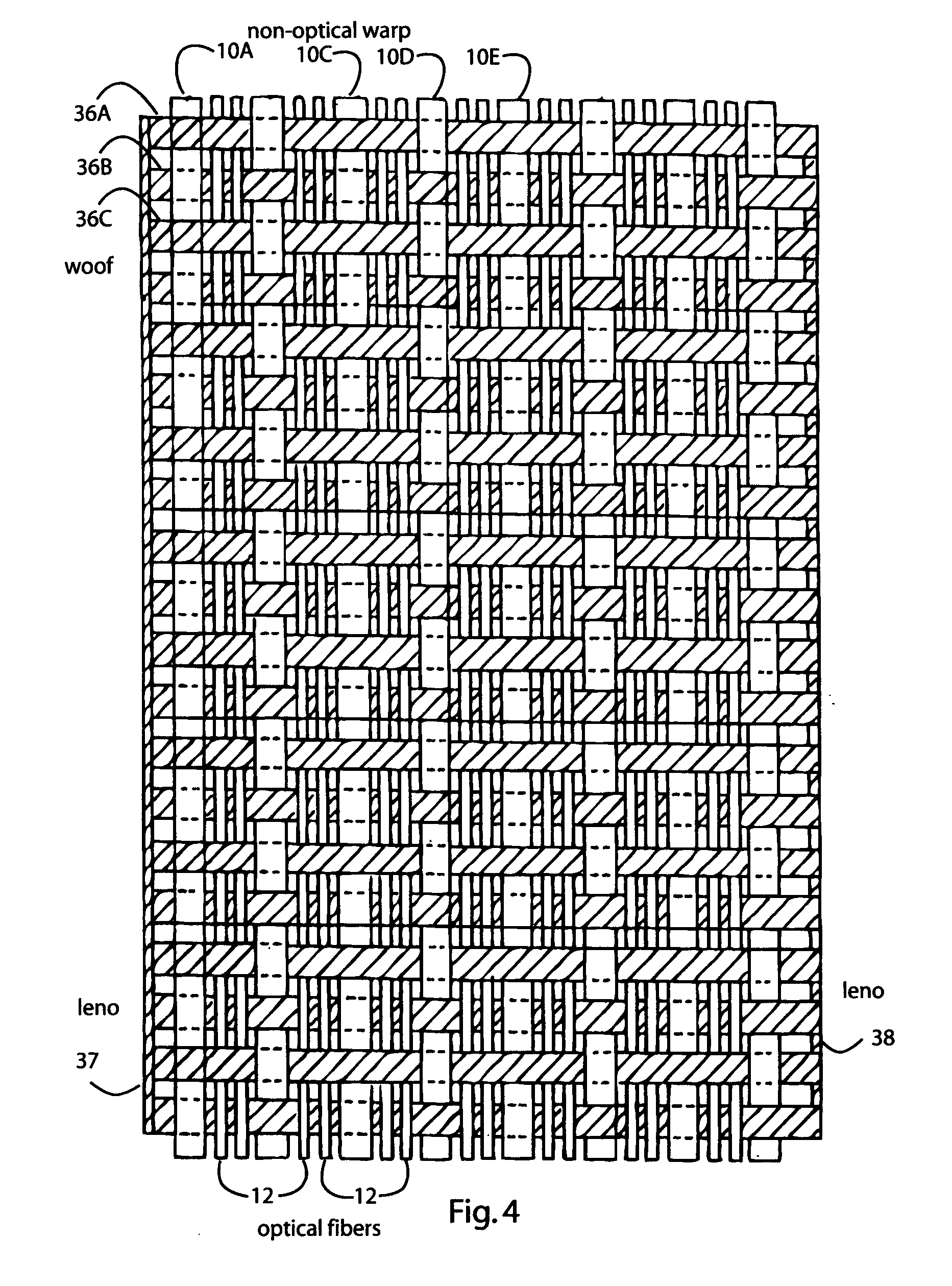
[0040]The system may use a fabric sheet containing fiber optic sens...


PUM

PropertyMeasurementUnit
radiusaaaaaaaaaa
diameteraaaaaaaaaa
wavelengthaaaaaaaaaa

Abstract

An optical sensing system detects pressure through attenuation of light in an optical fiber. This is particularly useful for measuring the weight and position of a load on a mat including multiple such optical fibers, which may be positioned in an automobile seat to determine theses parameters for a passenger in that seat. This information can be presented to an airbag deployment system in a form that will easily enable the airbag to be deployed (when needed) in a manner sensitive to the weight and position of the occupant. It provides based on this detection system a technique to suppress airbag deployment based on passenger profile. Further, the system and method use an optical fabric methodology such that loads, load movement, load position can be detected in vehicles. In applications for vehicles such as aircraft or boats, sensing weight, position and movement of cargo can warn an operator or pilot in sufficient time to correct dangerous shifts in weight within the cargo portion of the vehicle or to modify the operation of the vehicle to compensate for such shifts.

Description

BACKGROUND[0001]1. Field of the Invention[0002]The present invention relates to sensing loads, and more specifically to sensing loads through use of an optical fiber positioned so that weight pressing on the fiber will cause attenuation in light passing through the fiber.[0003]2. Description of the Related Art[0004]There are many applications in which it is useful to be able to sense loads automatically, and in particular to sense the position and weight of the load. One particular area in which such capability is desirable is in determining the weight and position of a passenger in an automobile seat in order to determine the most appropriate deployment of an airbag in the event of an accident and, for example, to suppress such deployment in certain cases such as where the passenger is a small child. The requirement of next generation airbag suppression systems on all vehicles is being mandated for full implementation for all cars in the year 2008. This poses a technical challenge ...

Claims


Application Information

Patent Timeline
Patent Type & Authority Applications(United States)
IPC IPC(8): G01L1/00G02B6/00G06F19/00
CPCG01G3/125B60R21/01534G01L1/243G01G19/4142G01L1/24G01G3/12G01G19/414
Inventor WIENER, PATRICIA
Owner CARR & FERRELL
Why Eureka
Try Eureka