[0011]The
present method and system of separating, monitoring and sampling
high pressure coiled tubing flow back fluid returns from
oil and natural gas wells allows an operator to quickly and safely identify the physical characteristics of the flow back return fluids by minimizing the hazards facing the operator. The greatest danger lies in the need for the operator to monitor and sample the returns to understand what is happening down the wellbore, especially
deep drilling and offshore wellbores where the returns are under pressures as high as 12,000 psi to 14,000 psi and greater.
[0013]
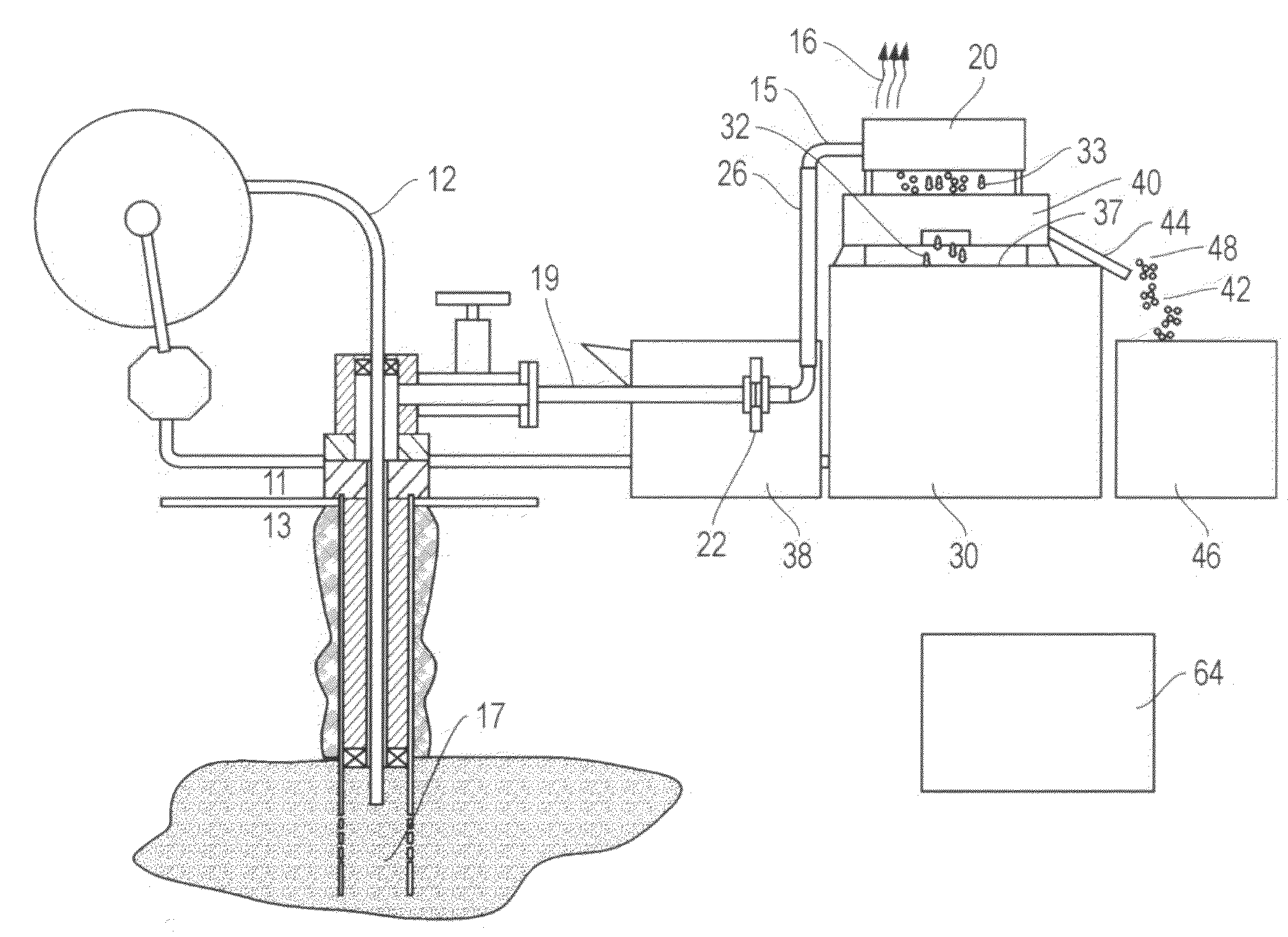
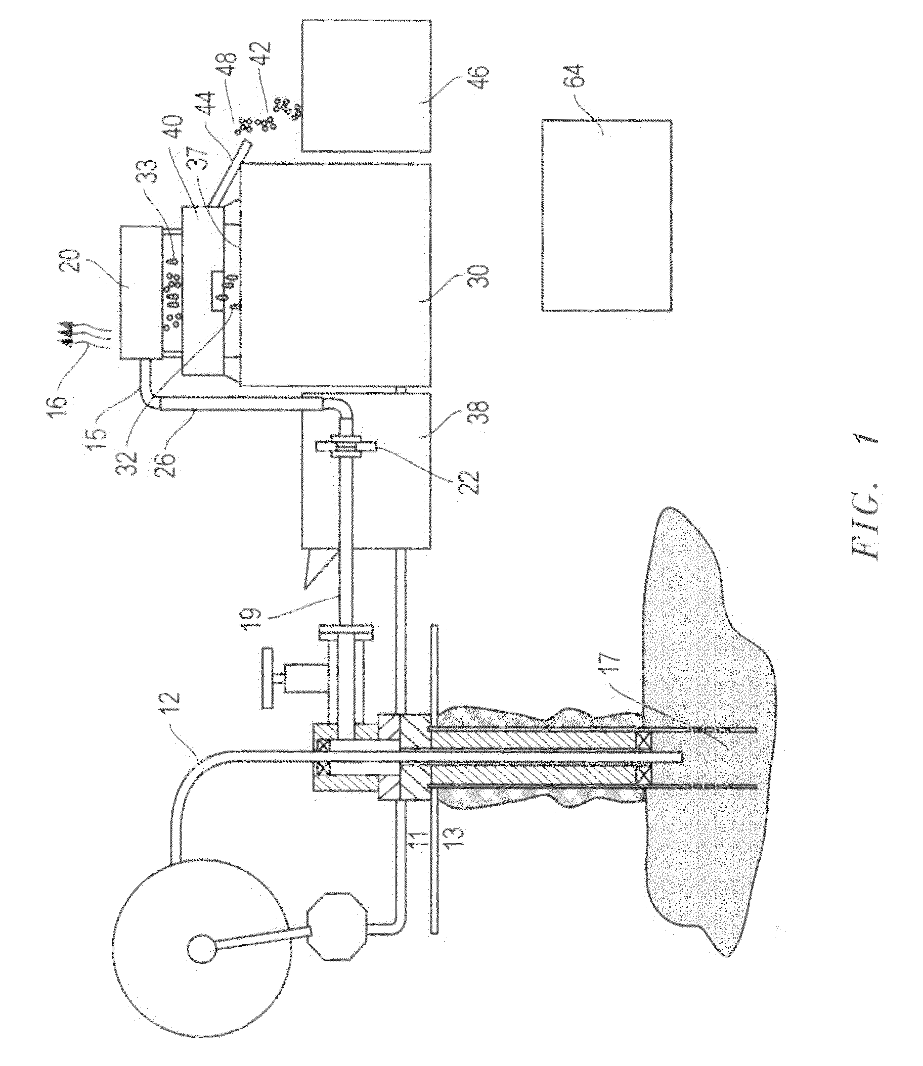
High pressure flowline
piping is used to connect the wellbore to one or more gas diffusers, which are rigidly and removably attached to a flow back tank. A
choke manifold, installed between the wellbore and gas diffuser, can be used to reduce the dangerously high pressures, which can sometimes exceed 12,000 psi. Advantageously, the connection between the wellbore and the gas diffusers has a means for a quick disconnect so that the gas diffusers can be installed rapidly. The gas diffusers remove the trapped gases from the fluid mixture, releasing them to the
atmosphere with the rest of the fluid mixture exiting from portals positioned on the underside of the gas diffusers.
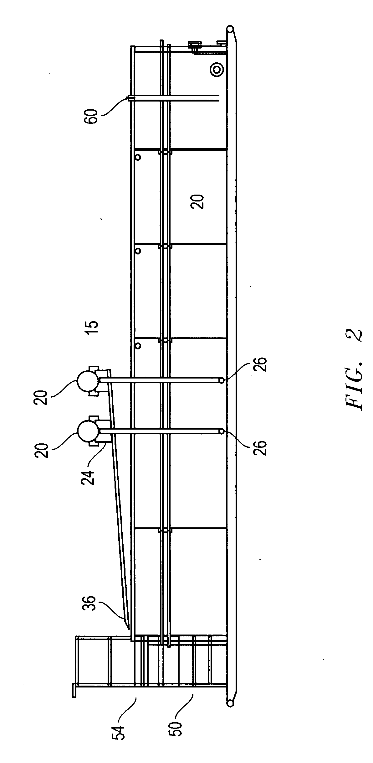
[0014]Preferably, a chute is fixedly attached to each gas diffuser to collect depressurized and decelerated fluid mixture. As a safety feature, the chute is positioned so that it directs the fluid towards the perimeter of the flow back tank. In one embodiment, a sampling site is located adjacent to the perimeter of the flow back tank and the chute is positioned for easier and
safer monitoring and sampling of the fluid mixture leaving the gas diffuser. In another embodiment, a means for ascending the flow back tank is utilized to reach the top of the flow back tank. The means for ascending the flow back tank can include a stairway, a ramp, a ladder or a motorized stairway. Preferably, it is positioned adjacent the perimeter of the flow back tank and the chute in order to provide better access to the sampling site. In an alternate embodiment, a means for sampling the fluid mixture within the flow back tank, such as a sampling carousel, is used, and it is also positioned adjacent to the chute.
[0015]In another aspect of this invention, a volume level indicator is used to determine the volume of the liquid within the flow back tank. Preferably, the volume level indicator is visible up to at least 30 feet from the flow back tank and is positioned on or near the perimeter of the flow back tank so that an operator may determine the level of the flow back tank without having to precariously look over the edge.
[0017]In another embodiment, a method for monitoring and sampling the flow back fluid returns of
oil and natural gas wells begins with pumping fluid returns, brought up from the wellbore, to one or more gas diffusers. The fluid returns comprise gases, liquids and solids. The gas diffusers are rigidly and removably attached to a flow back tank. The gases are then separated from the fluid returns by one or more gas diffusers and released to the
atmosphere. Next, the liquids and solids remaining within the degassed fluid are discharged from the one or more gas diffusers into a chute that directs the liquids and solids into a shale
shaker, wherein the solids are separated from the liquids. The solids are sent to a collection bin via a solids
discharge channel, and may be monitored and sampled as the solids travel down the solids
discharge channel for analysis at a solids sampling site. The liquids are then directed into the flow back tank via a liquids
discharge channel, where they may be monitored and sampled for analysis while en
route to the flow back tank at a liquid sampling site. In another embodiment of the method of this invention illustrating a second safety factor, the operator can safely monitor the liquids and solids in real time by positioning a platform and means for ascending the platform adjacent the flow back tank to observe the liquids or solids
coming out of the gas buster or shale
shaker and take samples of the materials for further analysis. Either the liquids or the solids, preferably both, can be analyzed to determine changes in downhole conditions.

