Smart fan clutch

a fan clutch and intelligent technology, applied in the direction of fluid couplings, couplings, machines/engines, etc., can solve the problems of lack of efficiency, difficult integration of precise control of vehicle engine fans, and inability to implemen

Active Publication Date: 2008-10-02
BEHR AMERICA
View PDF19 Cites 8 Cited by
  • Summary
  • Abstract
  • Description
  • Claims
  • Application Information

AI Technical Summary

Problems solved by technology

Vehicle manufacturers and OEMs have, however, had a difficult time integrating precise control over vehicle engine fans.
This has resulted in the widespread use of simple binary (on-off) type fan systems that lack efficiency but are possible to implement.

Method used


Image

  • Smart fan clutch
  • Smart fan clutch
  • Smart fan clutch

Examples


Embodiment Construction

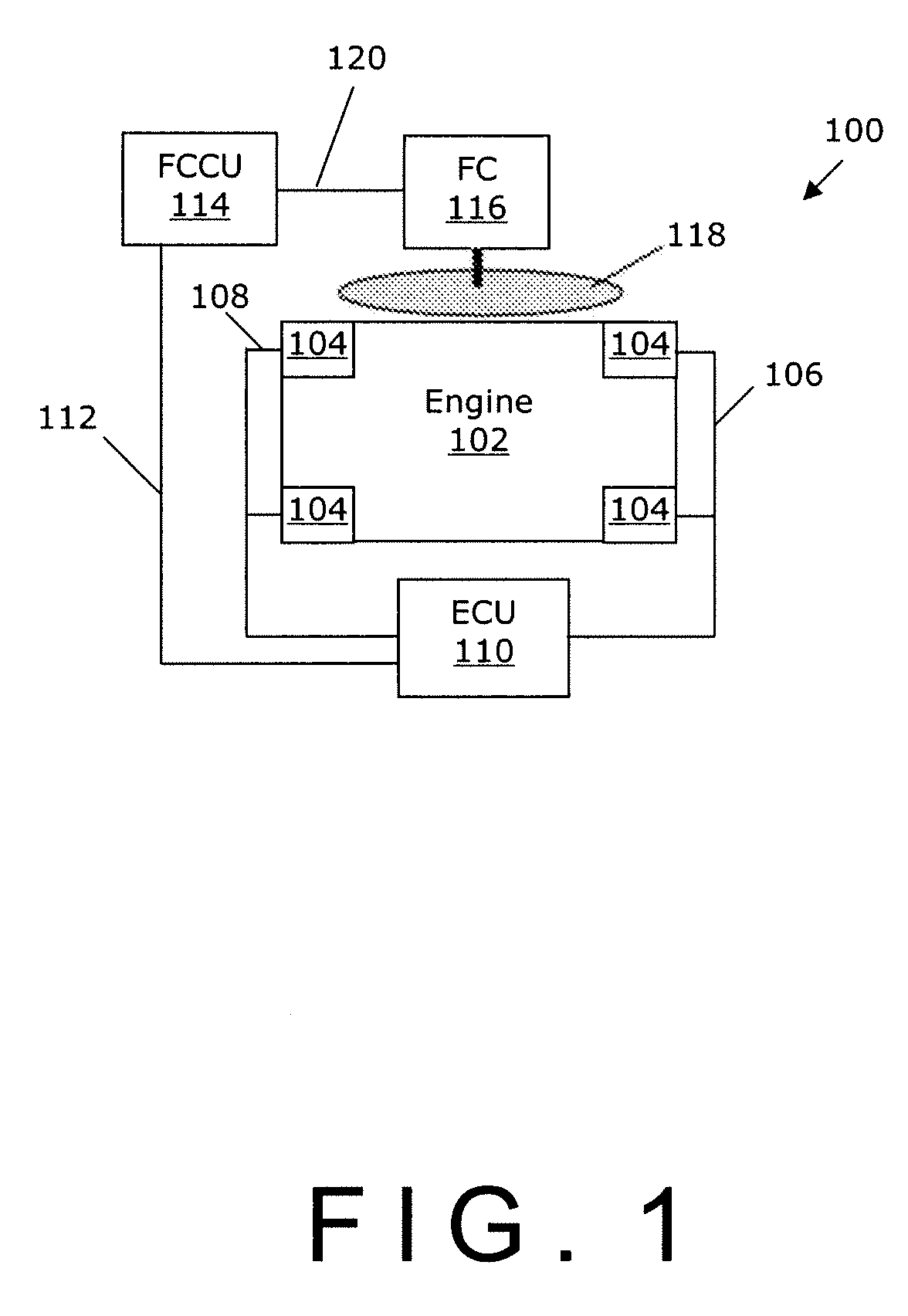
[0015]Referring to FIG. 1, there is shown a block diagram showing a vehicle system 100. While the system 100 is shown as a vehicle system, it will be appreciated that the principles described herein can be applied to other systems that require cooling. The system 100 has an engine 102 having a plurality of sensors 104. The sensors are attached, for example, to communications buses 106 and 108, which allow them to be in communication with engine control unit 110.

[0016]Engine control unit 110 is further in communication with fan clutch control unit 114 over bus 112, which is in a preferred embodiment a Controller Area Network (CAN) bus conforming to revision 2.0A and 2.0B of the CAN standard. The CAN bus transmits differential signals and has a built in cyclic redundancy check, thereby allowing for accurate data transmission in an electromagnetically noisy environment. Any number of different interfaces could be used depending on conditions, however, for example I2C, SPI (Serial Perip...


PUM


Abstract

Systems, methods and devices for the control of fans are presented. More specifically, embodiments of the present invention relate to a fan clutch control unit for a vehicle fan. The fan clutch control unit executes a control loop section and a strategy section to provide control functionality. The fan clutch control unit may be provided as a pre-packaged control board or integrated into a fan clutch.

Description

CROSS REFERENCE TO RELATED APPLICATIONS[0001]The present application claims benefit of priority to U.S. Provisional Application Ser. No. 60 / 920,819, filed Mar. 30, 2007, the entire contents of which is incorporated herein by reference.FIELD OF THE INVENTION[0002]The embodiments of the present invention relate generally to systems, methods and devices for controlling fans, including engine fans. More specifically, certain embodiments of the present invention relate to systems, methods and devices for controlling modulating fan clutches for engines via the use of discrete control units having embedded software and in communication with an engine or the control unit of an engine. Certain embodiments will be useful in heavy vehicle applications.BACKGROUND OF THE INVENTION[0003]In conjunction with increasingly demanding vehicle emission standards, the need for more precise control of machine cooling systems is being felt. In particular, vehicle emission standards are expected to become s...

Claims


Application Information

Patent Timeline
Patent Type & Authority Applications(United States)
IPC IPC(8): F16D28/00
CPCF01P7/048F01P2023/08
Inventor POWERS, JASONDEUTER, THOMAS
Owner BEHR AMERICA
Why Eureka
Try Eureka