Plasma-jet spark plug

a spark plug and plasma technology, applied in the direction of spark plugs, machines/engines, mechanical equipment, etc., can solve the problems of insulator damage and insulator damag

Inactive Publication Date: 2008-10-02
NGK SPARK PLUG CO LTD
View PDF4 Cites 10 Cited by
  • Summary
  • Abstract
  • Description
  • Claims
  • Application Information

AI Technical Summary

Benefits of technology

[0009]According to a first aspect there is provided a plasma-jet spark plug, comprising a center electrode and an insulator having an axial bore which extends in an axial direction. The insulator accommodates a front end face of the center electrode therein and holds the center electrode. A cavity is formed on the front end side of the insulator and assumes a concave shape defined by an inner circumference face of the axial bore and either a front end face of the center electrode or a plane surface including the front end face. A metal shell holds the insulator by surrounding a radial circumference of the insulator. The spark plug further comprises a ground electrode joined to the metal shell so as to be electrically connected thereto. The ground electrode is disposed on the front end side with respect to the insulator and has an opening portion to allow communicating between the cavity and the outside of the spark plug, wherein a plasma can be produced in the cavity along with a spark discharge between the center electrode and the ground electrode. The insulator and the ground electrode are disposed apart from each other in the axial direction, wherein the following relations are satisfied: 0<a<=0.5 [mm] and 0.1<=S<=10 [mm3] where “a” is a dimension of a clearance between the insulator and the ground electrode in the axial direction; and “S” is a volume of the cavity.
[0010]In addition to the first aspect, in a plasma-jet spark plug according to a second aspect, the insulator and the metal shell are disposed apart from each other in a radial direction perpendicular to the axial direction such that the following relation is satisfied: b<=1.1 [mm] where “b” is a dimension of a clearance between the insulator and the metal shell in the radial direction perpendicular to the axial direction.
[0011]In addition to the second aspect and according to a third aspect, dimension “b” satisfies the relation 0.1<=b<=1.1 [mm].
[0012]Further, according to a fourth aspect of the present invention, a plasma jet spark plug is provided having a center electrode and an insulator having an axial bore which extends in an axial direction. The insulator accommodates a front end face of the center electrode therein and holds the center electrode. A cavity is formed on the front end side of the insulator and assumes a concave sha

Problems solved by technology

However, when an insulator and a metal shell is formed with a strict dimensional control in the manufacturing of a plasma-jet spark plug and a front end face of the insulator comes in contact with an inner face of the ground electrode as in the plasma-jet spark plug according Patent Document 1 or 2, the insulator can be damaged due to a difference in thermal expansion coefficient of the materials constituting the insulator, the metal she

Method used


Image

  • Plasma-jet spark plug
  • Plasma-jet spark plug
  • Plasma-jet spark plug

Examples


experiment 1

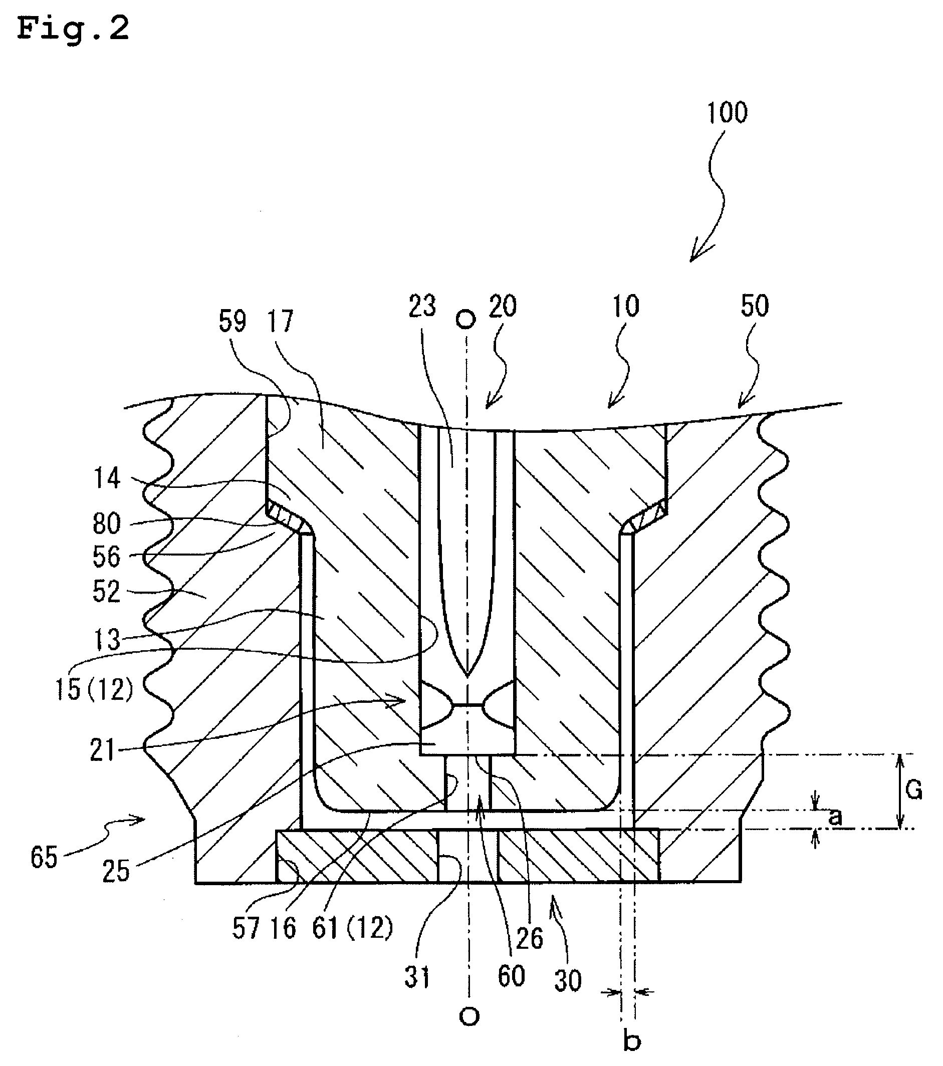
[0054]First, in order to study a relation between the dimension “a” of the first clearance, the volume S of the cavity 60 and the ignitability, a test was conducted. Several kinds of plasma-jet spark plugs (test samples) were produced. Each test sample had one of four kinds of insulator (each having a different inner diameter D so that the volume S of the cavity was either 5, 10, 15 or 20 mm3) with the first clearance dimension “a” ranging from 0.1 to 0.7 mm. The spark discharge gap dimension G in each sample was 3.0 mm, and the second clearance dimension “b” was 1.0 mm. Further, the first packing was not formed in the first clearance.

[0055]Each sample was mounted on a pressure chamber and subjected to ignitability test, charging the chamber with a mixture of air and C3H8 gas (air-fuel ratio: 22) to a pressure of 0.05 MPa (a gas-charging process). Next, the respective sample was connected to a power supply, which could supply energy of 150 mJ, so as to feed a high voltage thereto. T...

experiment 2

[0057]Next, a test was conducted in order to study a relation between the spark discharge gap dimension G, the second clearance dimension “b” and the ignitability. In this test, a plurality of samples of the plasma-jet spark plug was produced. Each sample had an insulator in which the long leg portion was formed such that the second clearance dimension “b” was either 0.5, 1.0, 1.1 or 1.5 mm. The spark discharge gap dimension G was within the range from 1.0 to 4.0 mm. Each sample had the first clearance dimension “a” of 0.5 mm. The spark discharge gap dimension G was adjusted by changing the depth of the cavity. At this time, the inner diameter D of each sample was determined and adjusted so that the volume S of the cavity was kept constant at 10 mm3 to compensate for the changes of the depth of the cavity. That is, this test was conducted using the limit value confirmed in Experiment 1, which obtained an ignitability of 100%. Further, similar to Experiment 1, the first packing was n...

experiment 3

[0061]Next, a test was conducted to confirm whether there is any improvement in the ignitability of the plasma-jet spark plug having the first packing in the first clearance thereof. In this test, a plurality of plasma-jet spark plugs was produced in which one of two kinds of insulator (one with the first packing placed in the first clearance, and the other without any first packing) was employed. The first clearance dimension “a” fell within the range from 0.3 to 0.9 mm. Each sample had the second clearance dimension “b” of 1.0 mm. The depth of the cavity of each sample was adjusted so that the spark discharge gap dimension G was set to 3.0 mm irrelevant of the first clearance dimension “a”. Further, the inner diameter D of each sample was determined and adjusted so that the volume S of the cavity was kept at 10 mm3. That is, this test was conducted using the limit value confirmed in Experiments 1 and 2, which obtained the ignitability of 100%.

[0062]Similar to Experiments 1 and 2, ...


PUM


Abstract

A plasma-jet spark plug comprising an insulator and a ground electrode which are disposed apart from each other in an axial direction (O) to prevent a damage of the insulator. The spark plug is capable of reducing an energy loss of the ejected plasma by defining a dimension of a clearance between the insulator and the ground electrode whereby deterioration of the ignitability of the plasma-jet spark plug is prevented. Clearance having a first clearance dimension “a” is formed between a front end of the insulator and the ground electrode. Since a volume S of a cavity formed at the front end side of the insulator is set to 10 mm3 or less, plasma formed in the cavity is prevented from spreading. Further, since the first clearance dimension “a” satisfies a<=0.5 mm, the plasma ejected from the cavity is ejected toward the outside of the spark plug while keeping sufficient energy, so that it is unlikely that an energy leak in the first clearance occurs on the way to an orifice.

Description

FIELD OF THE INVENTION [0001]The present invention relates to a plasma-jet spark plug producing plasma to ignite an air-fuel mixture in an internal-combustion engine.BACKGROUND OF THE INVENTION [0002]A spark plug is widely used in an automotive internal-combustion engine to ignite an air-fuel mixture by a spark discharge. In response to the recent demand for high engine output and fuel efficiency, it is desired that the spark plug has an increased ignitability to exhibit a higher ignition-limit air-fuel ratio and to achieve proper lean mixture ignition and quick combustion.[0003]Such a plasma-jet spark plug includes a center electrode and a ground electrode (external electrode), which is connected with a metal shell, defining a spark discharge gap therebetween, and an insulator (housing) made of ceramic or the like and surrounding the spark discharge gap so as to form a small discharge space, so-called a cavity (chamber). A spark discharge is generated through application of a high ...

Claims


Application Information

Patent Timeline
IPC IPC(8): H01T13/20
CPCH01T13/54H01T13/50H01T13/52H01T13/00H01T13/26
Inventor NAKAMURA, TORUKATO, TOMOAKI
Owner NGK SPARK PLUG CO LTD
Why Eureka
Try Eureka