Method of Testing an Electrochemical Device

a technology of electrochemical devices and electrochemical devices, which is applied in capacitor testing, fuel cell testing, electric vehicles, etc., can solve the problems of confined fuel cell testing methods, inability to implement testing in an application setting, and other loss terms identified, so as to achieve simple computation time and facilitate extended

Active Publication Date: 2008-10-02
EATON INTELLIGENT POWER LIMITED
View PDF5 Cites 26 Cited by
  • Summary
  • Abstract
  • Description
  • Claims
  • Application Information

AI Technical Summary

Benefits of technology

[0124]The advantage of obtaining the circuit parameters with the method described in section 4.5 is that it can be easily extended to find the parameters of each individual cell from the data shown in FIG. 11. This saves having to do individual tests on each cell, then individually obtaining the parameters of each cell. There are 30 circuit values to find, (5 for each of the 6 cells), and the computation time simply increases compared to finding the values of a single cell. Using the same convergence criteria, the circuit parameters were obtained (shown in table 3) and the simulation of the circuit with these parameters is also shown in FIG. 11. As can be seen, the simulated model results compare very well with the data from the stack.

Problems solved by technology

As a result, this fuel cell testing method is confined to a lab environment rather than an application setting.
However, other loss terms have been identified when a functioning Molten Carbonate Fuel Cell had been subjected to a current interrupt test [17].
However, this testing has not been implemented in an application setting, and essentially is restricted to a lab type environment.
A number of current interrupt tests are proposed for parameter identification, however, as stated by Larminie, unique determination of anode and cathode properties can not be achieved by this technique alone.
However, only a steady state comparison between experimental and modelled results was made, negating the effect of the capacitors present in the model.
However, this validation is somewhat unclear, as the capacitors in the ECM were replaced with constant phase elements and no circuit component values have been given.
It has been reported that certain DLC capacitors store charge due in part to faradic processes (limited electrochemical reactions), however this is a minor effect compared to the charge stored from non-faradic processes.

Method used


Image

  • Method of Testing an Electrochemical Device
  • Method of Testing an Electrochemical Device
  • Method of Testing an Electrochemical Device

Examples


experimental embodiment

3.4 Specific Experimental Embodiment

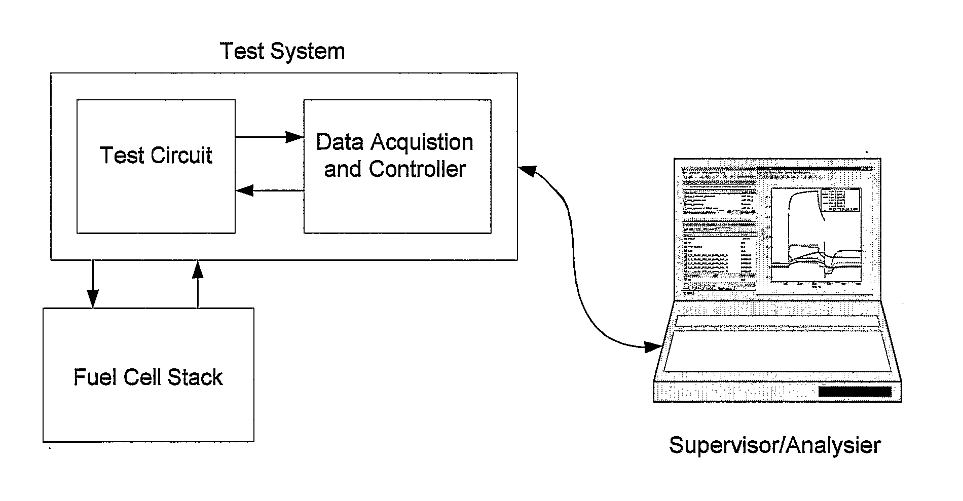
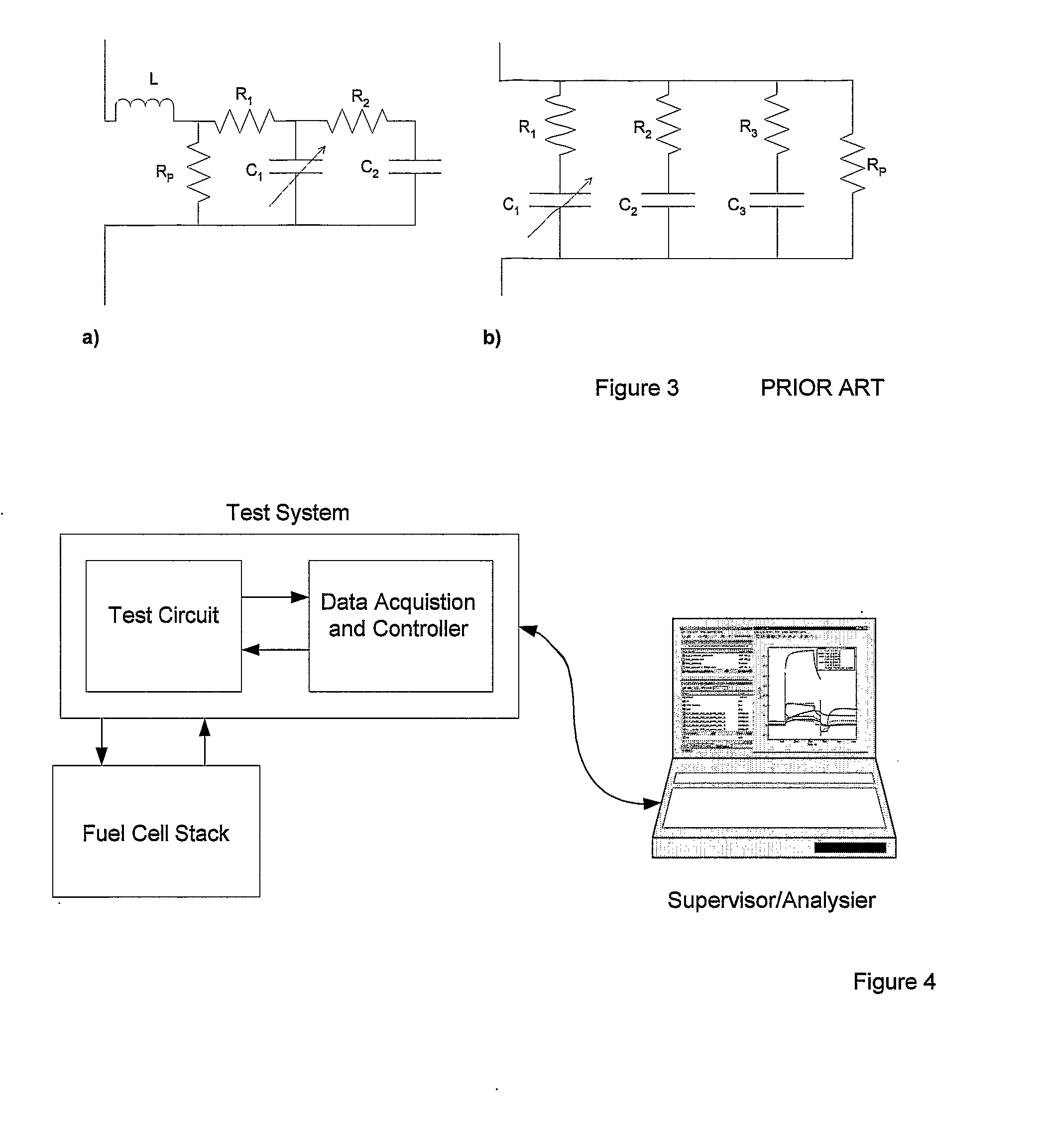
[0079]The testing procedure has been implemented on a small PEM fuel cell stack manufactured by MerCorp. The stack contained 6 cells stacked in series, each with an active area of 32 cm2 and a Nafion based membrane. The stack design is completely symmetrical i.e. the gas flow-field design and electrode structures for the anode and cathode are identical. The test circuit component values were R1TC=100Ω and R2TC=4.9Ω, with VTC being set at a variety of values depending on what test was being implemented. For data acquisition and control, an HP 34970A Data Acquisition / Switch Unit was used, which contains an internal digital multi-meter for measurement purposes. The Data Acquisition / Switch Unit contained an HP 34901A 20-Channel Multiplexer card (enabling all of the cell voltages, stack terminals and the voltage across R1TC to be measured) as well as a HP 34907A Multifunction Module (which provided outputs for control of the test circuit). A P4m 2 GHz ...


PUM

PropertyMeasurementUnit
areaaaaaaaaaaa
temperatureaaaaaaaaaa

Abstract

Methods and associated apparatus for testing an electrochemical device, such as a fuel cell. A first method involves charging the fuel cell during a charge period; discharging the fuel cell during a discharge period; and monitoring the response of the fuel cell during at least part of the discharge period or the open-circuit response of the fuel cell. Another method involves testing the fuel cell when the fuel cell is in a passive state in which substantially no electrochemical reactions are taking place in the fuel cell. simultaneously applying a stimulus to all of the devices, and independently monitoring the response of each of the devices to the stimulus. Further methods involve obtaining test data from a device being tested; obtaining equivalent circuit values; calculating sets of simulation data for each equivalent circuit value; comparing sets of simulation data with the test data; and selecting one of the equivalent circuit values based on the comparison. This method allows all circuit parameters of each cell in a stack to be obtained from only one quick test.

Description

FIELD OF THE INVENTION[0001]The present invention relates to various methods and associated apparatus for testing an electrochemical device. Certain aspects of the invention relate to the testing of a fuel cell, but others are applicable to a range of devices, including (but not limited to) fuel cells and double-layer capacitors.BACKGROUND OF THE INVENTION1. Testing Procedures[0002]Proton Exchange Membrane (PEM) Fuel Cell testing is wide ranging in terms of measured properties, and testing techniques. Testing objectives may include identifying specific properties, evaluating overall performance, or determining the state of a functioning fuel cell for control purposes. Measured fuel cell properties include individual loss terms, membrane hydration, and specific electrochemical properties such as the charge transfer resistance. A number of material properties, such as the membrane ionic resistance, have been measured ex situ using a variety of techniques [1, 2, 3]. However, most fuel ...

Claims


Application Information

Patent Timeline
Patent Type & Authority Applications(United States)
IPC IPC(8): G01R31/36G01R27/26G01R31/01H01M8/04
CPCG01R27/2605G01R31/028G01R31/362G01R31/3658G01R31/3662H01M8/04305H01M8/04552Y02E60/50G01R31/3835G01R31/389G01R31/396G01R31/64
Inventor PAGE, SHANNON CHARLESAL-ANBUKY, ADNANKRUMDIECK, SUSAN PRAN
Owner EATON INTELLIGENT POWER LIMITED
Why Eureka
Try Eureka