Eureka AIR delivers breakthrough ideas for toughest innovation challenges, trusted by R&D personnel around the world.

Coplanar waveguide resonator and coplanar waveguide filter using the same

Inactive Publication Date: 2008-10-02
NTT DOCOMO INC
View PDF4 Cites 6 Cited by
  • Summary
  • Abstract
  • Description
  • Claims
  • Application Information

AI Technical Summary

Benefits of technology

[0016]The resonance frequency f1 of the center conductor can be split and the center conductor can be made to resonate at a frequency f2 lower than the frequency f1 by providing the base stub having the first collateral line conductor. This means that, in designing and fabricating a coplanar waveguide resonator having the resonance frequency f2, a center conductor having a physical length corresponding to an electrical length equivalent to a quarter wavelength or a half wavelength at the resonance frequency f1 can be used. That is, according to the present invention, the total length of the coplanar waveguide resonator can be reduced. In addition to the reduction in total length, since the coplanar waveguide resonator has a simple structure in which the base stub is additionally provided in the gap section between the center line conductor and the ground conductor, the footprint of the coplanar waveguide resonator on the dielectric substrate is reduced. Therefore, according to the present invention, the coplanar waveguide resonator is downsized compared with conventional coplanar waveguide resonators, and since such coplanar waveguide resonators are used, the coplanar waveguide filter is also downsized compared with conventional coplanar waveguide filters.

Problems solved by technology

However, the area of the center conductor is increased to increase the capacitance at the part at which the electrical field is concentrated, and therefore, it is difficult to reduce the footprint of the quarter-wavelength coplanar waveguide resonator on the dielectric substrate, while the total length of the coplanar waveguide resonator can be reduced.
However, the quarter-wavelength coplanar waveguide resonator requires an area on which the center conductor having a physical length corresponding to an electrical length equivalent to a quarter wavelength is disposed, and therefore, it is difficult to reduce the footprint of the quarter-wavelength coplanar waveguide resonator on the dielectric substrate.
As described above, even if the total length of the coplanar waveguide resonator can be reduced, the coplanar waveguide resonator cannot be sufficiently miniaturized.

Method used


Image

  • Coplanar waveguide resonator and coplanar waveguide filter using the same
  • Coplanar waveguide resonator and coplanar waveguide filter using the same
  • Coplanar waveguide resonator and coplanar waveguide filter using the same

Examples


Embodiment Construction

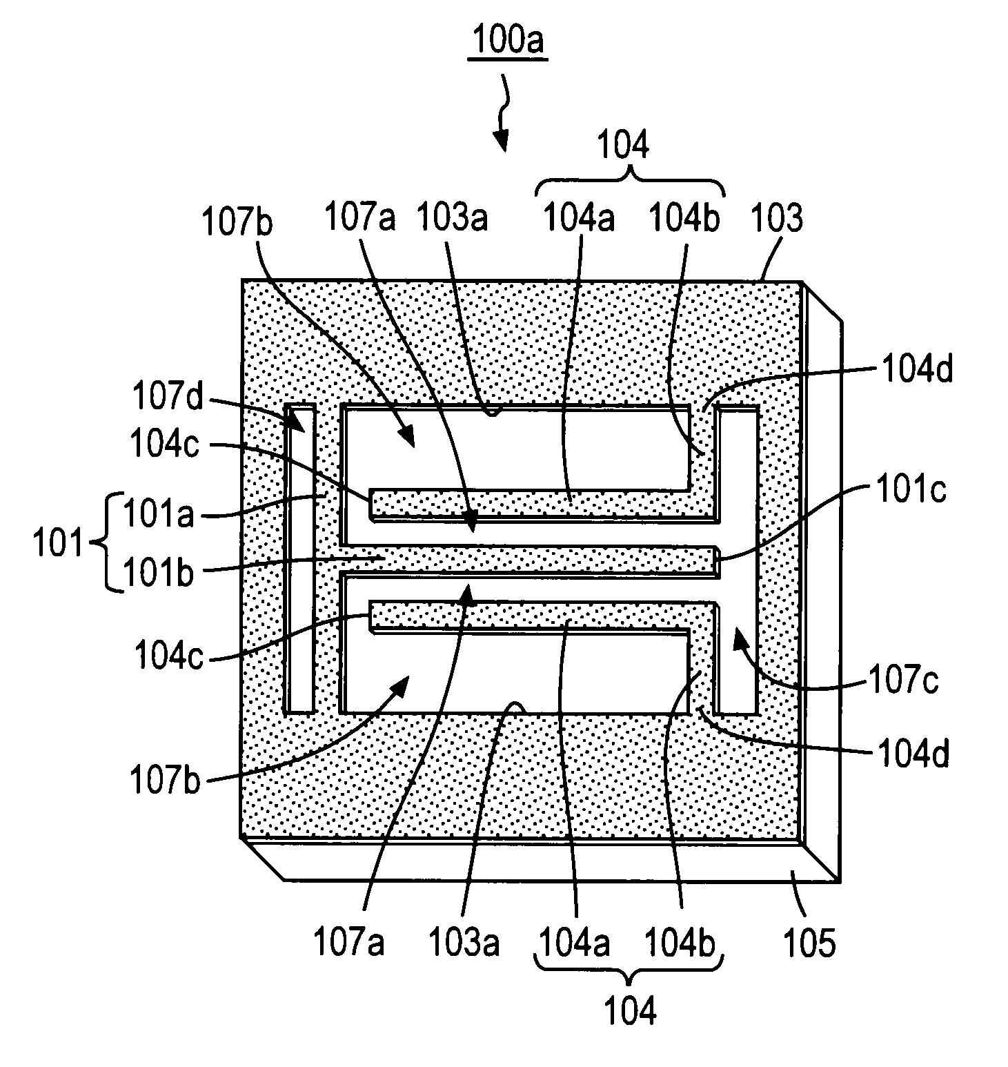
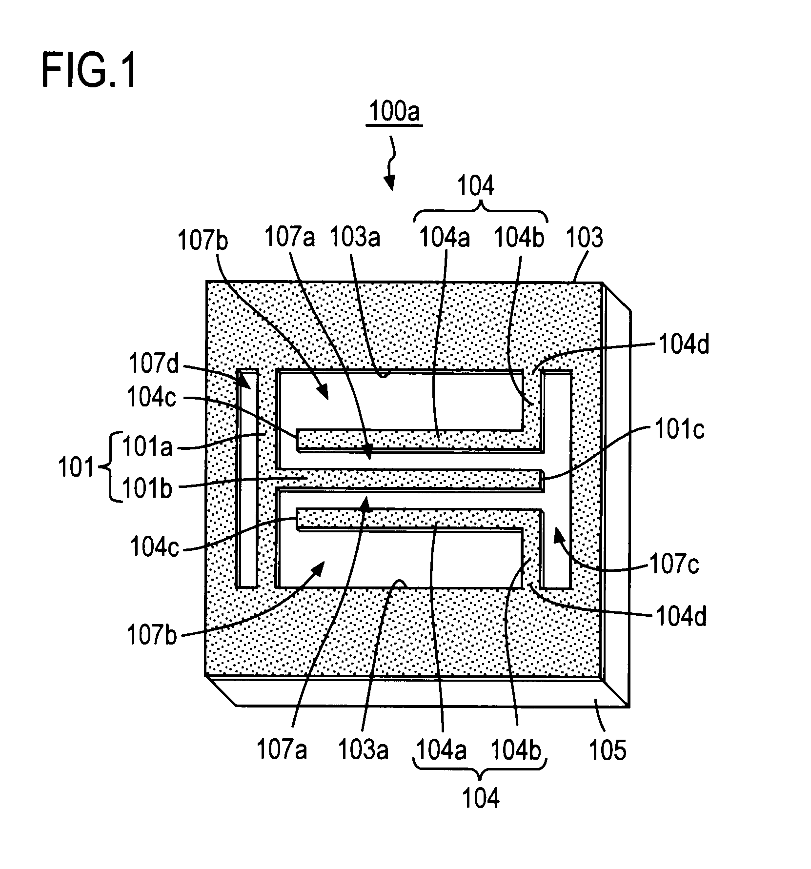
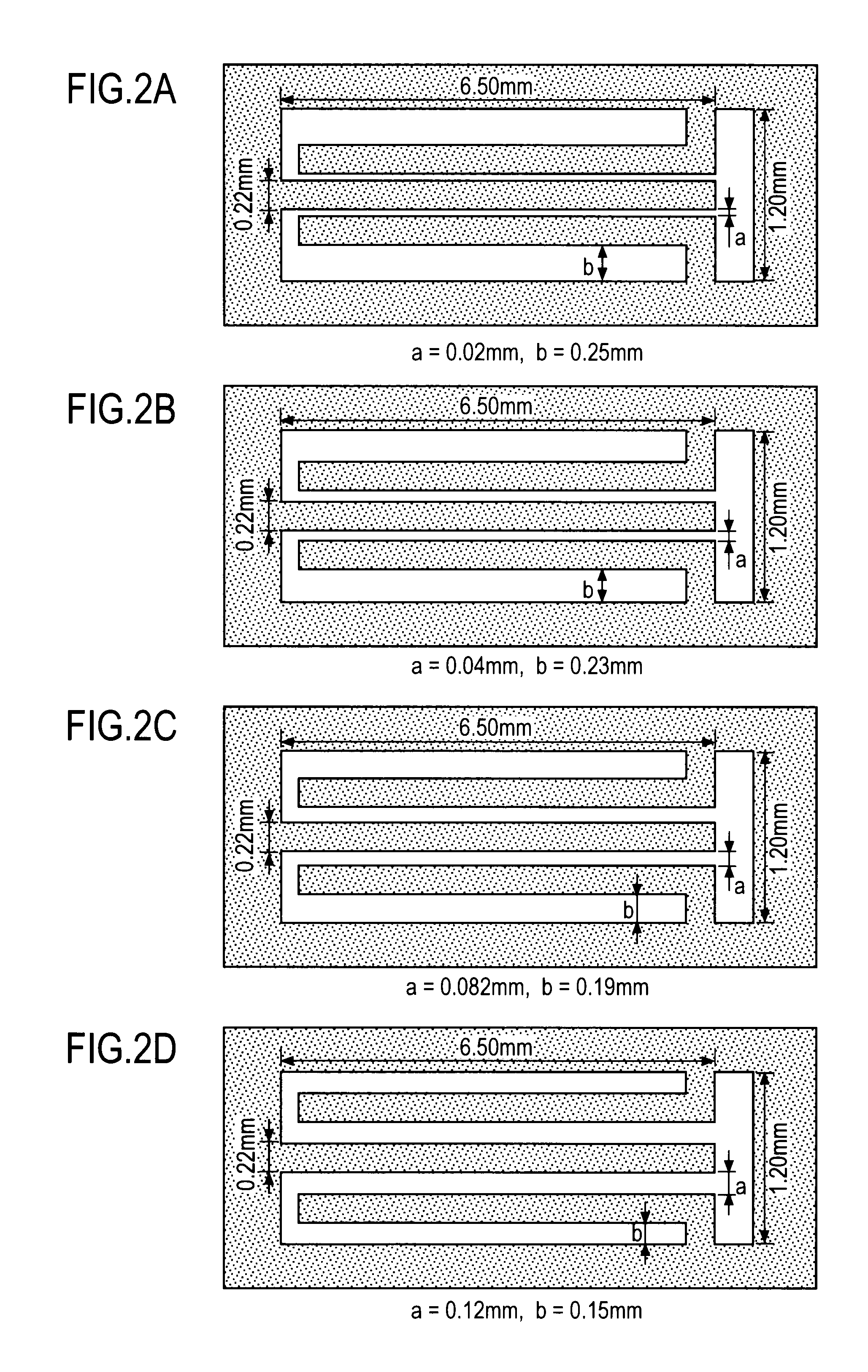
[0069]Embodiments of the present invention will be described with reference to FIGS. 1 to 26. In FIGS. 1, 2A to 2G, 4 to 8, 9A to 9I and 11 to 13, illustration of input / output terminals actually disposed on the opposite ends of the coplanar waveguide resonator shown in each drawing (the left and right ends of the coplanar waveguide resonator when each drawing is viewed straight from the front) is omitted. In all the drawings except for FIG. 1, illustration of a dielectric substrate 105 is omitted.

[0070]FIG. 1 shows a coplanar waveguide resonator according to an embodiment of the present invention. In this embodiment, the coplanar waveguide resonator is a quarter-wavelength coplanar waveguide resonator. A quarter-wavelength coplanar waveguide resonator 100a shown in FIG. 1 comprises a ground conductor 103 disposed on a surface of a dielectric substrate 105 illustrated as a rectangular shape, and a center conductor 101 and two line conductors 104 formed by patterning the ground conduc...


PUM


Abstract

A coplanar waveguide resonator (100a) has a center conductor (101) formed on a dielectric substrate (105) that has a line conductor (a center line conductor) (101b) extending in the input / output direction, a ground conductor (103) that is disposed on the dielectric substrate (105) across a gap section from the center conductor (101), and a line conductor (a base stub) (104) formed as an extension line from the ground conductor (103), and a part of the base stub (104) constitutes a line conductor (a first collateral line conductor) (104a) disposed in parallel with the center line conductor (101b).

Description

BACKGROUND OF THE INVENTION[0001]1. Field of the Invention[0002]The present invention relates to a coplanar waveguide resonator and a coplanar waveguide filter using the same. More specifically, it relates to miniaturization of the same.[0003]2. Description of the Related Art[0004]Recently, a coplanar waveguide filter using one or more coplanar waveguide resonators has been proposed as a filter used in a transceiver device for microwave or millimeter wave communications. A coplanar waveguide resonator has a line conductor (a center conductor) having an electrical length equivalent to a half wavelength or a quarter wavelength and a ground conductor disposed across a predetermined space from the center conductor that are formed on the same surface of a dielectric substrate. Thus, for example, the circuit pattern is formed on only one side of the dielectric substrate, and no via hole is needed to form a short-circuited stub. As a result, the coplanar waveguide resonator has advantages ...

Claims


Application Information

Patent Timeline
IPC IPC(8): H01P1/20
CPCH01P1/2013H01P7/08H01P1/203
Inventor SATOH, KEIKOIZUMI, DAISUKENARAHASHI, SHOICHI
Owner NTT DOCOMO INC
Why Eureka
Eureka Blog
Learn More