Roller bearing

a roller bearing and roller technology, applied in the direction of sliding contact bearings, mechanical equipment, machines/engines, etc., can solve the problems of excessive internal stress in the cage, restricted axial displacement of the cage, and possible torque loss

Inactive Publication Date: 2008-10-02
JTEKT CORP
View PDF6 Cites 3 Cited by
  • Summary
  • Abstract
  • Description
  • Claims
  • Application Information

AI Technical Summary

Benefits of technology

[0007]A problem that the invention is to solve is to provide a roller bearing that can achieve the diameter reduction thereof by omitting the inner ring, and that can prevent the cage thereof from being axially and radially displaced.
[0016]Thus, in a roller bearing for rotatably supporting, for example, a rotating shaft disposed in a housing of an engine, raceway surfaces are formed on the inner peripheral surface of an outer ring and the outer peripheral surface of the rotating shaft. Consequently, the inner ring can be omitted. Accordingly, the diameter reduction (miniaturization) of the roller bearing can be achieved. The peripheral surface of each of the rollers is radially contacted with the raceway surfaces formed on the inner peripheral surfaces of the body portions of the outer ring and the outer peripheral surface of the rotating shaft. The outer peripheral surface of each of the annular portions of the cage is disposed (at an axial end portion) so as to face the inner peripheral surface of an associated one of the rib portions of the cage via a predetermined clearance. Consequently, the outer peripheral surface of each of the annular portions of the cage can be guided by the inner peripheral surface of an associated one of the rib portions of the outer ring. Accordingly, the radial displacement of the cage can be prevented. Thus, a torque loss can be prevented from being caused due to the sliding resistance of the cage. Also, the occurrence of a loss (or the generation of a chip) due to the generation of an excessive internal stress in the cage can be prevented.
[0019]According to the invention, preferably, the roller bearing is configured so that a radial leading end surface of each of the projection portions of the cage is disposed so as to face the inner peripheral surface of an associated one of the body portions of the outer ring via a predetermined clearance at the axial intermediate portion, and that a clearance S1 from the outer peripheral surface of each of the pair of annular portions of the cage to an associated one of the inner peripheral surfaces of the pair of rib portions of the outer ring is formed so as to be smaller than a clearance S2 from the radial leading end surface of each of the projection portions of the cage to a peripheral inner surface of a corresponding one of the body portions of the outer ring. When a centrifugal force due to engine rotation acts upon the cage, the inner peripheral surface of each of the rib portions of the outer-ring split pieces touches the outer peripheral surface of the annular portion of the cage before the inner peripheral surface of each of the body portions of the outer-ring split pieces touches the radial leading end surface of the projection portion of the cage. Consequently, the radial displacement of the cage can be prevented in good time. Accordingly, a torque loss can be prevented from being caused due to the sliding resistance between the radial leading end surface of the projection portion of the cage and the inner peripheral surface (raceway surface) of each of the body portions of the outer ring. Also, a loss (or a chip) can be prevented from being generated due to the generation of an excessive internal stress in the cage by causing the cage to touch the outer ring at the split place.
[0021]Further, a roller holding surface, which is inclined so as to become closer to the pocket towards a radially outward side thereof, can be formed on each of the projection portions of the cage. The roller can be prevented by forming such a roller holding surface from slipping off the cage at the assembly of the bearing. Additionally, the radial relative displacement (disengagement) between the roller and the cage due to the centrifugal force can be prevented.
[0023]In a case where the cage is of the split type, chamfering is performed on the split place, so that inclined surfaces are formed, which incline (like, e.g., a letter “V”) to the split surfaces from two directions, respectively. More specifically, the first inclined surfaces formed on the leading end surfaces of the projection portions are arranged so as to butt against each other. Further, the second inclined surfaces formed on the leading end surfaces of the projection portions are arranged so as to butt against each other. Consequently, even in a case where the split surfaces of the cage vibrate (or are displaced from each other) during the rotation of the rotating shaft, the cage is difficult to touch (or collide with) the split places on the outer-ring split pieces. Thus, a loss (or a chip) can be prevented from being generated due to an excessive internal stress generated in the cage.
[0024]Incidentally, in a case where the end surface of the roller touches the inner-side end surface of the rib portion of the outer ring, and where the cage is formed so that the axial length of each of the projection portions of the cage is smaller than the length of each of the rollers, the axial displacement of the cage can be prevented while the projection portions of the cage are non-contacted with the outer ring. Accordingly, a torque loss can be prevented from being generated due to the sliding resistance of the cage. Also, a loss (or a chip) can be prevented from being generated due to the generation of an excessive internal stress in the cage.

Problems solved by technology

However, because the bearing, from which the inner ring is omitted, lacks a means for fixing the bearing to the rotating shaft, it is necessary to restrict the axial displacement of a cage.
Further, in the case of such a rotating shaft, a large centrifugal force acts upon the roller bearing with engine rotation.
Especially, in the case of a crankshaft, the outer ring of the bearing is split into two parts, there is a fear that when the cage is moved (displaced) in an axial direction and a radial direction so as to touch an outer-ring splitting position, an excessive internal stress is generated in the cage.
Thus, there are still fears that a torque loss may be caused due to the sliding resistance generated therebetween, and that excessive internal stresses may be generated in the cage.
Additionally, the radial displacement of the cage due to the centrifugal force due to the engine rotation is not sufficiently considered.

Method used


Image

  • Roller bearing
  • Roller bearing
  • Roller bearing

Examples


embodiment 1

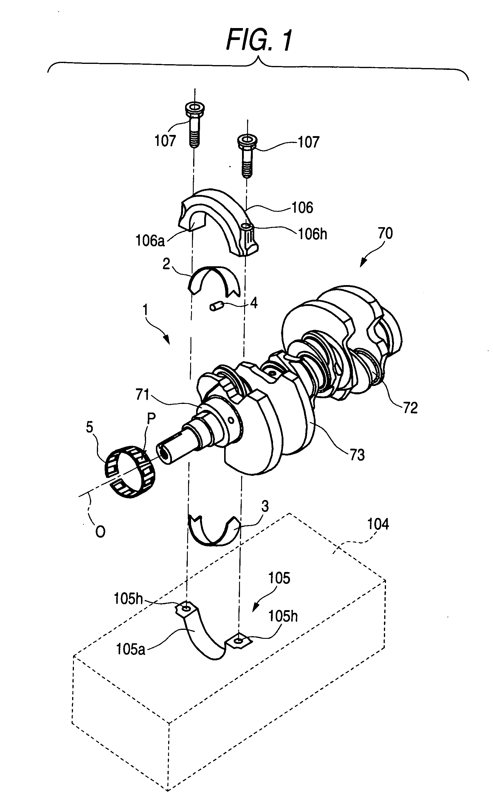
[0034]Hereinafter, embodiments of the invention are described with reference to the accompanying drawings. FIG. 1 is an exploded perspective view illustrating an example of a crankshaft having a roller bearing according to the intention. A crank journal 71 of a crankshaft 70 (corresponding to the rotating shaft) is put on a seat 105 (corresponding to the outer ring fixing member) formed integrally with a cylinder block (housing) 104 of an engine. The seat 105 and a cap member 106 (corresponding to the outer ring fixing member), which is disposed so as to upwardly face the seat 105 across the crank journal 71, are clamp-fixed to each other via a needle roller bearing (hereunder referred to simply as a roller bearing) 1. That is, the crank shaft 70 is rotatably supported by the roller bearing 1 on the cylinder block 104.

[0035]More specifically, paired internal thread holes 105h, and 105h are formed in the seat 105. Paired insertion holes 106h, and 106h are formed in the cap member 106...

embodiment 2

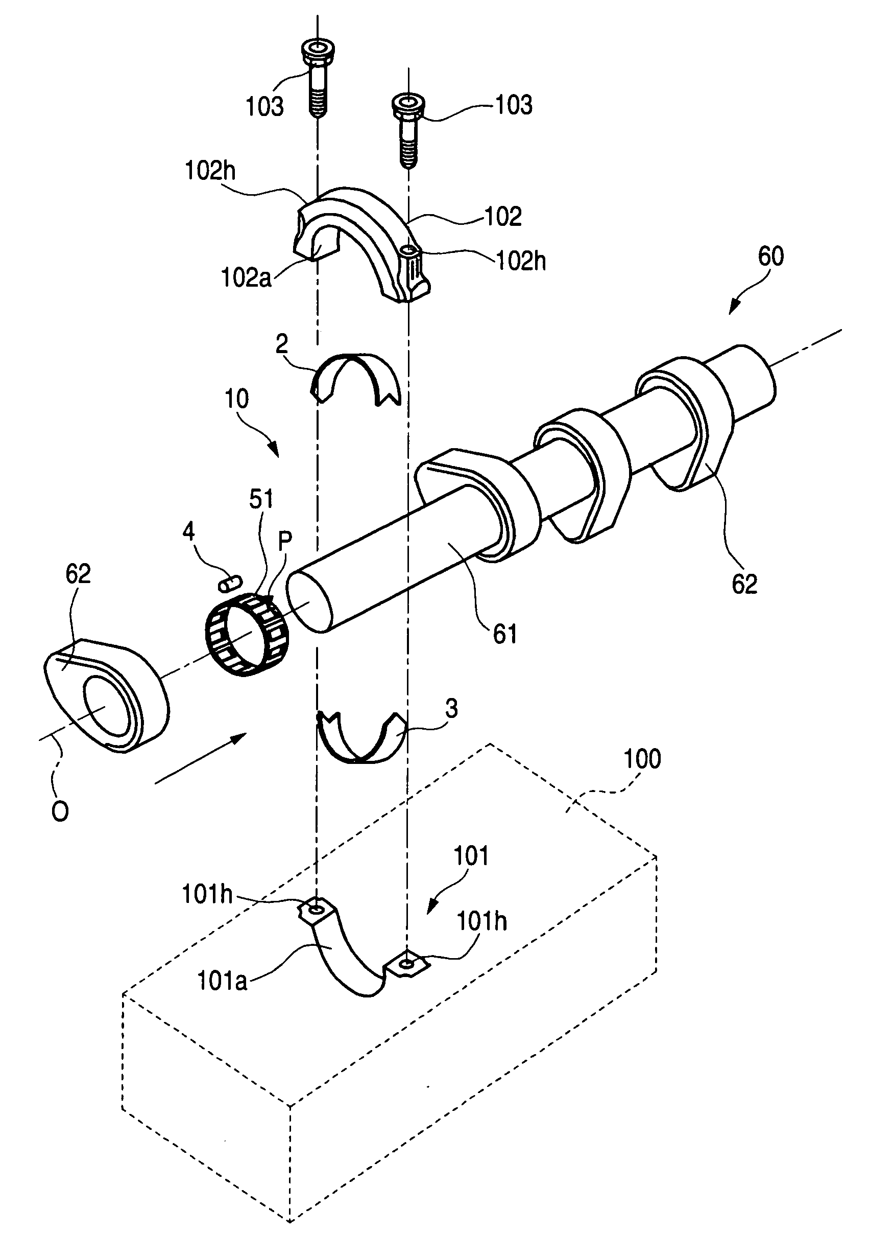
[0050]FIG. 5 is an exploded perspective view illustrating an example of a builtup cam shaft having a roller bearing according to the invention. A builtup camshaft 60 (corresponding to the rotating shaft) has a cam lobe 62 attachable and detachable from the direction of an axis line O. Thus, an integral type cage, which can not be circumferentially split, can be used as a cage 51 for a needle roller bearing (hereunder sometimes referred to simply as a roller bearing) 10.

[0051]A cam journal 61 of the builtup camshaft 60 is put on a seat 101 (corresponding to the outer ring fixing member) formed integrally with a cylinder block (housing) 100 of an engine. The seat 101 and a cap member 102 (corresponding to the outer ring fixing member), which is disposed so as to upwardly face the seat 101 across the cam journal 61, are clamp-fixed to each other via a roller bearing 10. That is, the builtup camshaft 60 is rotatably supported by the roller bearing 10 on the cylinder head 100.

[0052]More ...


PUM


Abstract

The clearance between the outer peripheral surface of an annular portion of a cage and the inner peripheral surface of each of rib portions of outer-ring split pieces is set to be smaller than the clearance between the radial end surface of a projection portion of the cage and the inner peripheral surface of each of body portions of the outer-ring split pieces. When a centrifugal force due to engine rotation acts upon the cage, the inner peripheral surface of each of the rib portions of the outer-ring split pieces touches the outer peripheral surface of the annular portion of the cage before the inner peripheral surface of each of the body portions of the outer-ring split pieces touches the radial end surface of the projection portion of the cage. Thus, the radial displacement of the cage can be prevented in good time.

Description

BACKGROUND OF THE INVENTION[0001]1. Field of the Invention[0002]The present invention relates to a roller bearing and, more particularly, to a roller bearing suitable for rotating shafts, such as a crankshaft and a camshaft, disposed in engine housings.[0003]2. Related Art[0004]Recently, roller bearings have generally been used for rotatably supporting rotating shafts, such as a crankshaft and a camshaft, disposed in engine housings (e.g., a cylinder block and a cylinder head). In such a case, an inner ring of the roller bearing can be omitted therefrom by utilizing the outer peripheral surface of the rotating shaft directly as a raceway surface. Thus, the diameter-reduction (miniaturization) of the roller bearing can easily be achieved by simultaneously maintaining load capacity. However, because the bearing, from which the inner ring is omitted, lacks a means for fixing the bearing to the rotating shaft, it is necessary to restrict the axial displacement of a cage. Further, in the...

Claims


Application Information

Patent Timeline
Patent Type & Authority Applications(United States)
IPC IPC(8): F16C33/46
CPCF01L1/047F01L2001/0476F01L2001/054F01L2101/00F16C9/02F16C17/02F16C21/00F16C33/46F16C33/4694F16C33/60F16C19/466F16C2360/18F01L2301/00
Inventor WASEDA, YOSHITAKAOKUMURA, TSUYOSHI
Owner JTEKT CORP
Why Eureka
Try Eureka