Implantable centrifugal blood pump with hybrid magnetic bearings

a centrifugal, magnetic bearing technology, applied in the direction of positive displacement liquid engine, prosthesis, liquid fuel engine, etc., can solve the problems of mechanical work, inapplicability of rolling element bearings to blood pumps, and notorious wear and failure of rotating shaft seals, etc., to achieve low heat dissipation, low attractive force, and compact size

a centrifugal, magnetic bearing technology, applied in the direction of positive displacement liquid engine, prosthesis, liquid fuel engine, etc., can solve the problems of mechanical work, inapplicability of rolling element bearings to blood pumps, and notorious wear and failure of rotating shaft seals, etc., to achieve low heat dissipation, low attractive force, and compact size

US20080240947A1Inactive Publication Date: 2008-10-02UNIV OF VIRGINIA ALUMNI PATENTS FOUND +2

Image

  • Implantable centrifugal blood pump with hybrid magnetic bearings
  • Implantable centrifugal blood pump with hybrid magnetic bearings
  • Implantable centrifugal blood pump with hybrid magnetic bearings

Examples


Embodiment Construction

[0037]Reference will now be made to the drawings in which the various elements of systems and methods of this disclosure will be given numeral designations and in which the invention will be discussed so as to enable one skilled in the art to make and use the invention. It is to be understood that the following description is only exemplary of the principles of the invention as claimed, and should not be viewed as narrowing the pending claims.

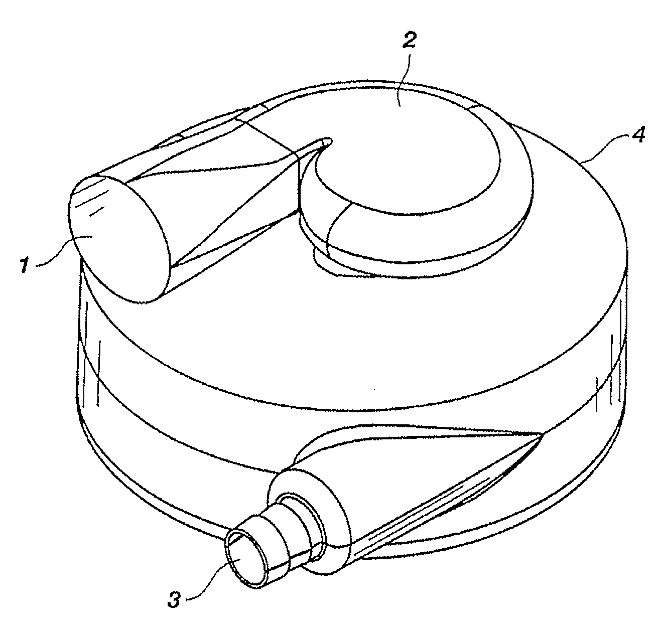
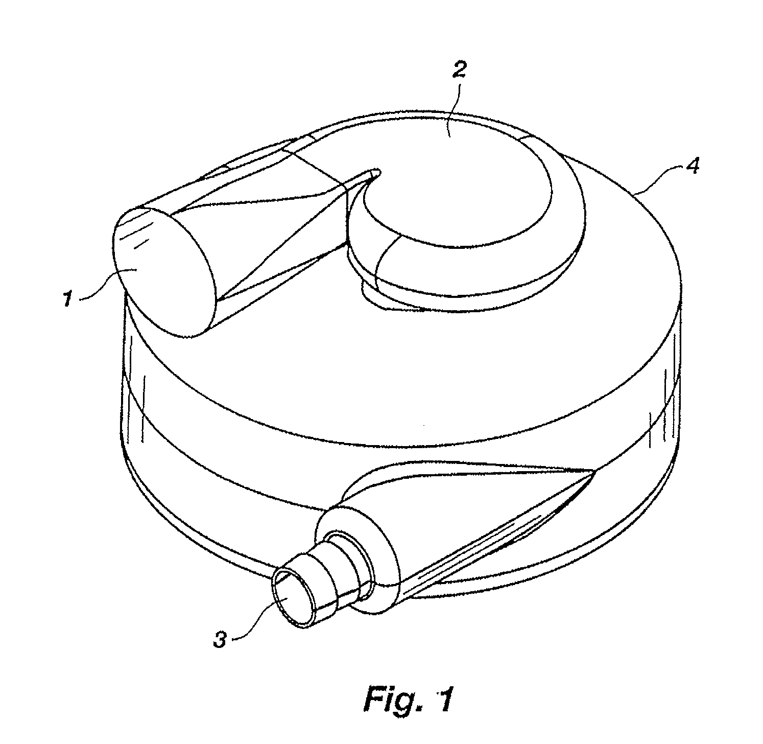
[0038]A perspective view of the assembled pump of the preferred embodiment is shown in FIG. 1. The pump generally comprises a housing 4 with an inlet 1, flow turning structure 2, and outlet 3. The flow turning structure 2 is configured to redirect incoming fluid flow through an acute angle in a gentle, low thermal manner using a compact structure. The turning structure is configured such that flow swirls around the inlet in a logarithmic spiral configuration, equalizing the flow rate and pressure entering the inlet. Additionally, this spiral in...


PUM


Abstract

A pump for pumping sensitive fluids, such as blood, has no mechanical contact between the impeller and any other structure.

Description

RELATED APPLICATION[0001]This application is a continuation of and claims priority to U.S. patent application Ser. No. 09 / 673,922, filed Oct. 24, 2001, entitled “Hybrid Magnetically Suspended and Rotated Centrifugal Pumping Apparatus and Method,” which is the National Stage of International Application No. PCT / US99 / 08870, filed Apr. 22, 1999, entitled “Implantable Centrifugal Blood Pump With Hybrid Magnetic Bearings,” which claims priority from abandoned U.S. patent application Ser. No. 09 / 064,352, filed Apr. 22, 1998, entitled “Implantable Centrifugal Blood Pump With Hybrid Magnetic Bearings,” which was a continuation-in-part of U.S. patent application Ser. No. 08 / 850,598, filed May 2, 1997, entitled “Hybrid Magnetically Suspended and Rotated Centrifugal Pumping Apparatus and Method,” now U.S. Pat. No. 6,074,180, which claims priority from U.S. Provisional Patent Application No. 60 / 016,856, filed May 3, 1996, entitled “Hybrid Magnetically Suspended and Rotated Centrifugal Pumping A...

Claims


Application Information

Patent Timeline
02 Oct 2008
Publication
US20080240947A1
IPC
F04B17/00; B63H1/02; A61F2/24; A61M1/10; F04D29/046; A61M1/12; F04D13/02; F04D29/048; F16C39/06
CPC
A61M1/101; F04D29/048; F05B2200/23; F16C32/0448; F04D13/0666; F16C2360/44; A61M1/1015; A61M1/1031
Inventors
ALLAIRE, PAUL E.; BEARNSON, GILL B.