Anti-lock hydraulic braking system, in particular for motorized two-wheel vehicles

a technology of anti-locking and hydraulic braking, which is applied in the direction of braking system, braking action transmission, transportation and packaging, etc., can solve the problems of preventing the use of such a braking system in particular in two-wheel vehicles with inexpensive materials, and the complexity of the device is required, so as to reduce the braking pressure, prevent a negative pressure, and improve the quality of control

Inactive Publication Date: 2008-10-09
FTE AUTOMOTIVE GMBH & CO KG
View PDF13 Cites 10 Cited by
  • Summary
  • Abstract
  • Description
  • Claims
  • Application Information

AI Technical Summary

Benefits of technology

[0008]The object of the invention is to provide an anti-lock hydraulic braking system, in particular for motorized two-wheel vehicles, which is simpler and less expensive than the above prior art and which, in the case of ABS control, is essentially free of disruptive feedback effects on the main brake cylinder.SUMMARY OF THE INVENTION
[0010]The hydraulic braking system designed in this way is firstly characterized in that it manages entirely without any electromagnetically operated switching valves for the pressure modulation in the skid-controlled operating phase. Compared to the prior art, this construction not only lowers the costs of the braking system as a whole but also advantageously reduces the size and weight of the actual pressure modulator. The hydraulic braking system according to the invention is thus particularly recommended for use on smaller or lower-performance motorized two-wheel vehicles, for example on scooters.
[0014]Preferably, the volume equalization device is a spring pressure reservoir. These reservoirs have a characteristic that can easily be set via the spring force and are easily commercially available at a low price as a mass-produced part.
[0016]Although there are in principle different possibilities for changing the conveying volume of the hydraulic pump, it is preferred in particular for cost reasons and with regard to easy control to drive the hydraulic pump by means of an electric motor, the rotational speed of which can be controlled in order to vary the volume flow produced by the hydraulic pump. The hydraulic pump may in principle be any motor-driven oil pump, e.g. a gear pump. However, with regard to high pressure resistance, low costs and a small size, preference is given to the use of a roller cell pump. The electric motor for driving the pump is preferably a brushless DC motor, which is characterized by excellent dynamics, a high efficiency, low wear and thus a long service life, a good overload capacity, a low weight and, last but not least, low noise generation.
[0018]In principle, it is possible to configure the switching valve—as in the above prior art—in such a way that the switching valve in its switched position interrupts, i.e. blocks, the connection between the main brake cylinder and the wheel brake cylinder in both possible flow directions. However, it is preferred if the switching valve is designed in such a way that the switching valve in its switched position acts as a non-return valve which allows a reduction in braking pressure on the wheel brake cylinder via the main brake cylinder. On the one hand, the switching valve thus switched into its switched position therefore prevents any more pressure from being added to the wheel brake circuit via the main brake cylinder in the case of ABS control. On the other hand, however, the switching valve thus switched into its switched position makes it possible to take account of a driver's desired pressure decrease, i.e. the driver in the case of ABS control on the main brake cylinder reduces the actuating force and opens the switching valve located in its switched position, which leads to pressure relief in the wheel brake circuit section between the switching valve and the wheel brake cylinder.
[0019]A pressure sensor may also be provided, by means of which the braking pressure in the wheel brake circuit can be detected. On the one hand, the quality of control can be improved by such a pressure detection. On the other hand, it is thus easily possible to prevent a negative pressure from being generated on the wheel brake cylinder due to the suction effect of the hydraulic pump.

Problems solved by technology

Although the above-described braking system is advantageously free of feedback on account in particular of the blocking effect of the inlet valve in the case of ABS control, i.e. the ABS pressure control shocks caused by the switching processes of the outlet valve are not transmitted to the main cylinder and thus the brake pedal, it is considered to be a disadvantage of this prior art that a relatively high device complexity is required which prevents the use of such a braking system in particular in inexpensive two-wheel vehicles.

Method used


Image

  • Anti-lock hydraulic braking system, in particular for motorized two-wheel vehicles
  • Anti-lock hydraulic braking system, in particular for motorized two-wheel vehicles
  • Anti-lock hydraulic braking system, in particular for motorized two-wheel vehicles

Examples


Embodiment Construction

OF EMBODIMENTS

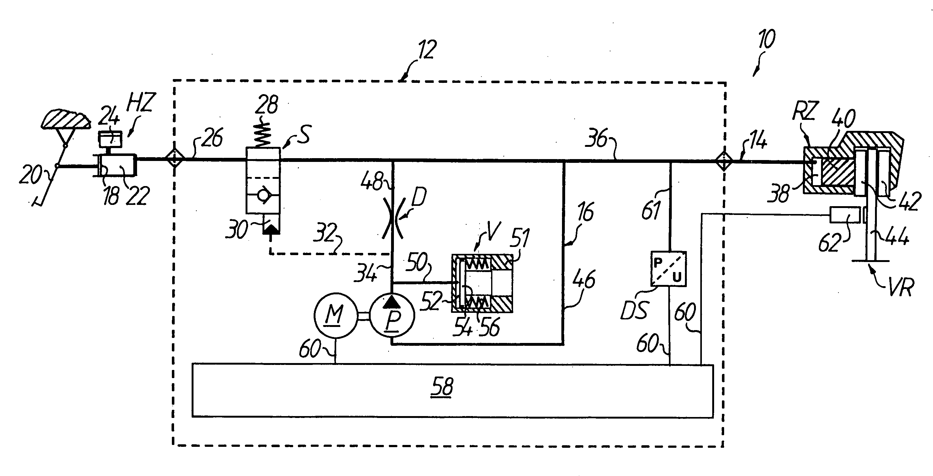
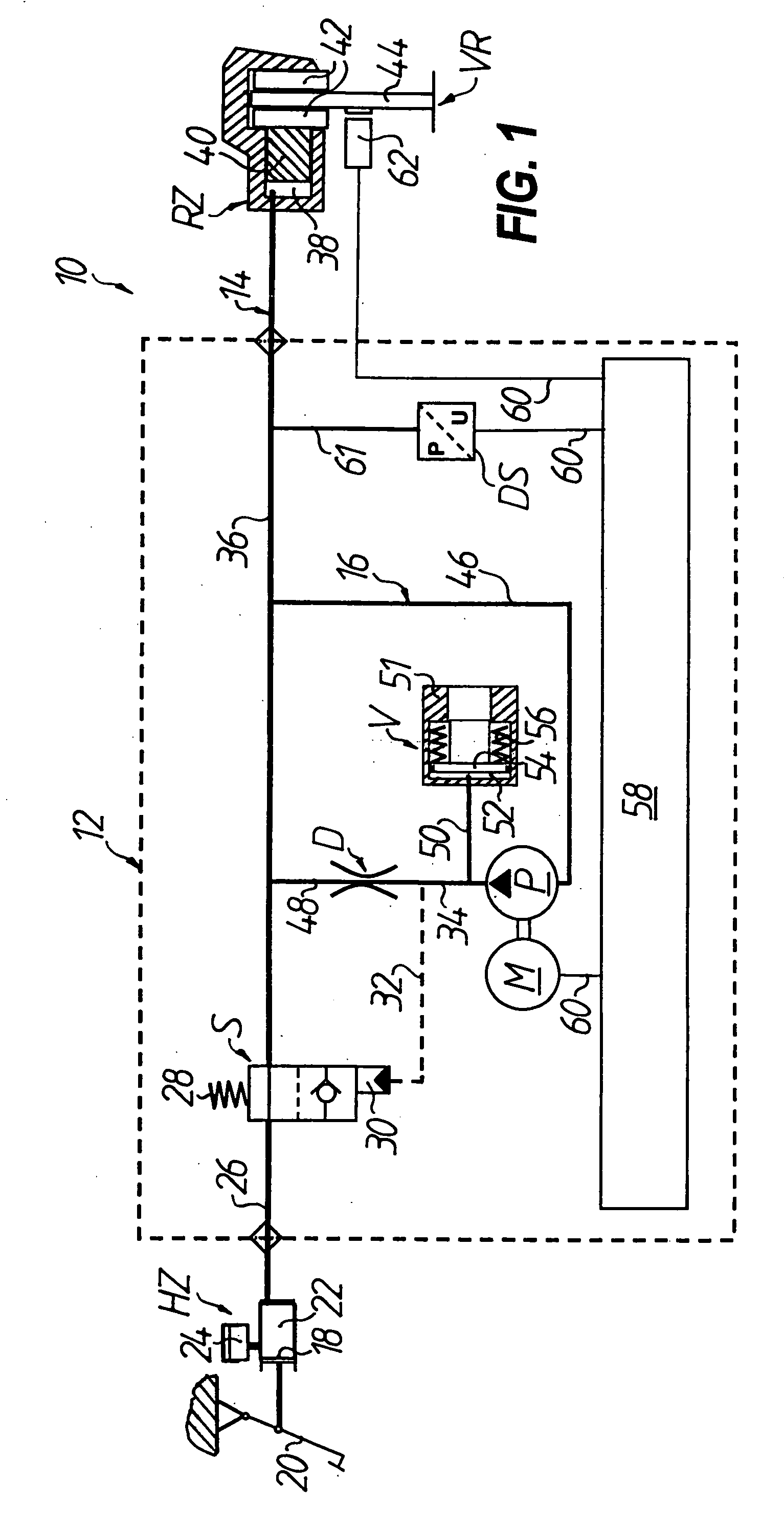
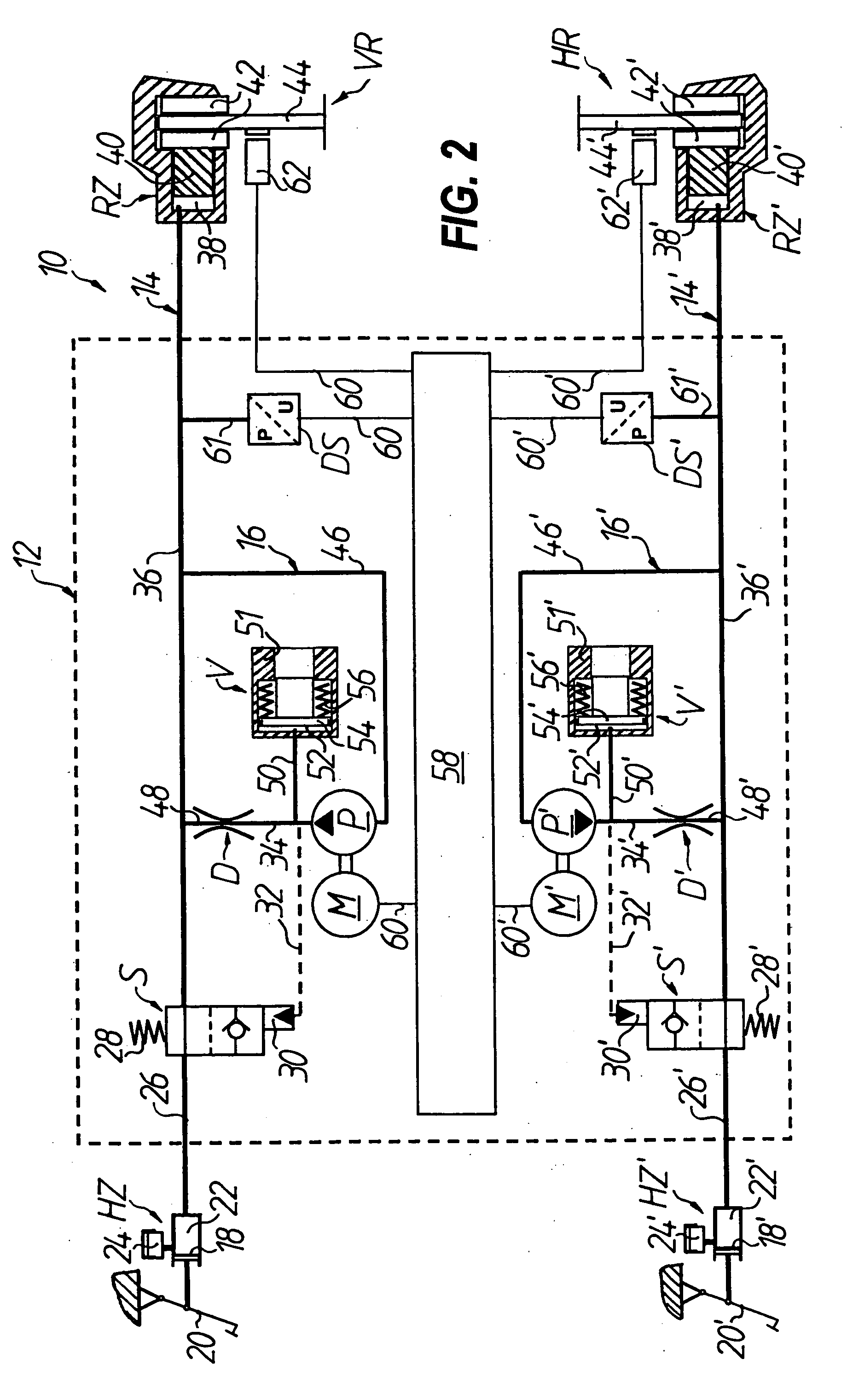
[0024]In FIG. 1, an anti-lock hydraulic braking system for a motorized two-wheel vehicle is generally denoted by 10, of which only the part of the system which acts on the front wheel VR is shown. The braking system includes a main brake cylinder HZ and a wheel brake cylinder RZ and also a pressure modulator which is connected therebetween and is generally denoted by 12. Seen hydraulically, the part of the braking system 10 which acts on the front wheel VR can be divided into a wheel brake circuit 14, which includes the main brake cylinder HZ, the wheel brake cylinder RZ and a switching valve S connected therebetween, and an auxiliary pressure circuit 16 which is connected in parallel between the switching valve S and the wheel brake cylinder RZ on the wheel brake circuit 14. The auxiliary pressure circuit 16 generally includes a hydraulic pump P for producing a volume flow, a throttle device D which is arranged downstream of the hydraulic pump P, and a volume equaliza...


PUM


Abstract

An anti-lock hydraulic braking system has a wheel brake circuit with a main brake cylinder, wheel brake cylinder and switching valve, and an auxiliary pressure circuit, connected in parallel between the switching valve and wheel brake cylinder on the wheel brake circuit. With ABS control, the switching valve can be switched from a basic position, where it hydraulically connects the main brake cylinder and wheel brake cylinder, to a switched position where it prevents a build-up of braking pressure on the wheel brake cylinder via the main brake cylinder, while the braking pressure on the wheel brake cylinder can be modulated by the auxiliary pressure circuit.

Description

TECHNICAL FIELD[0001]The invention relates to an anti-lock hydraulic braking system. In particular, the invention relates to an anti-lock hydraulic braking system for motorized two-wheel vehicles, as recently demanded by transport experts for safety reasons in general for motorized two-wheel vehicles.[0002]An anti-lock system, generally also known as an anti-lock braking system (ABS), in principle ensures that when, during a braking process with a braking pressure occurring on the wheel brake cylinder, a certain slowing threshold on the braked wheel is exceeded so that the wheel threatens to lock, the wheel braking pressure is reduced to below a second slowing threshold on this wheel. For this, it may be necessary to reduce the wheel braking pressure to zero. Thereafter, the wheel braking pressure is increased again until either the wheel is excessively braked again or the braking pressure defined by the driver is reached.PRIOR ART[0003]In the prior art, there is no lack of suggesti...

Claims


Application Information

Patent Timeline
Patent Type & Authority Applications(United States)
IPC IPC(8): B60T13/16
CPCB60T8/3225B60T8/4283
Inventor DRESCHER, WALTER
Owner FTE AUTOMOTIVE GMBH & CO KG
Why Eureka
Try Eureka