
Color image processing system and method thereof

a color image and processing system technology, applied in the field of color image processing system, can solve the problems of poor gradient characteristics of a dark part of an output image, color to be output, color separation/tonal correction, etc., and achieve the effect of flexible color conversion

Active Publication Date: 2008-10-09
CANON KK
View PDF3 Cites 13 Cited by
  • Summary
  • Abstract
  • Description
  • Claims
  • Application Information

AI Technical Summary

Benefits of technology

[0012]An object of the present invention is to provide a color image processing system and a method thereof capable of color conversion flexibly dealing with significant concern on gradient characteristics of a dark part or color difference, and correction in which balance of the whole of the output color gamuts is considered.

Problems solved by technology

If a color gamut of the source profile and the output color gamut differ from each other significantly, a problem will occur in a color to be output.
Accordingly, there occurs a problem in that all chromaticity points within a range of lightness values of minL_src to minL_dst are mapped on minL_dst, causing gradation collapse.
Since only a fixed color conversion table can be stored in a destination (printer) profile, some source profiles to be set may cause a problem that the gradient characteristics of a dark part of an output image are poor.
However, in Japanese Patent Laid-Open No. 2006-081080, since lightness correction is performed using a weighting function only in lightness direction, it is not possible to address a case in which the shape of the output color gamut of the dark part is distorted.
Moreover, since similar correction is performed also in the color reproduction region, the parts except for the dark parts may be corrected similarly, resulting in poor matching accuracy.
Moreover, in Japanese Patent Laid-Open No. 10-200773 (1998), a method is proposed which changes compression processing of Gamut (a color gamut of each of a monitor and a printer etc.) depending on the maximum / minimum lightness values of an input image signal, however, if processing is performed on every input image, long time will be necessary for processing.
Moreover, in some images, since color difference should be paid greater attention than gradient characteristics, there is a problem in this method, that such cases cannot be addressed flexibly.
Moreover, when the same source profile and the same image are input into a plurality of printers existing on a network as in FIG. 17, due to difference of the output color gamut (Gamut) of each of the printers, it is difficult to obtain output image giving the same impression.

Method used


Image

  • Color image processing system and method thereof
  • Color image processing system and method thereof
  • Color image processing system and method thereof

Examples


first embodiment

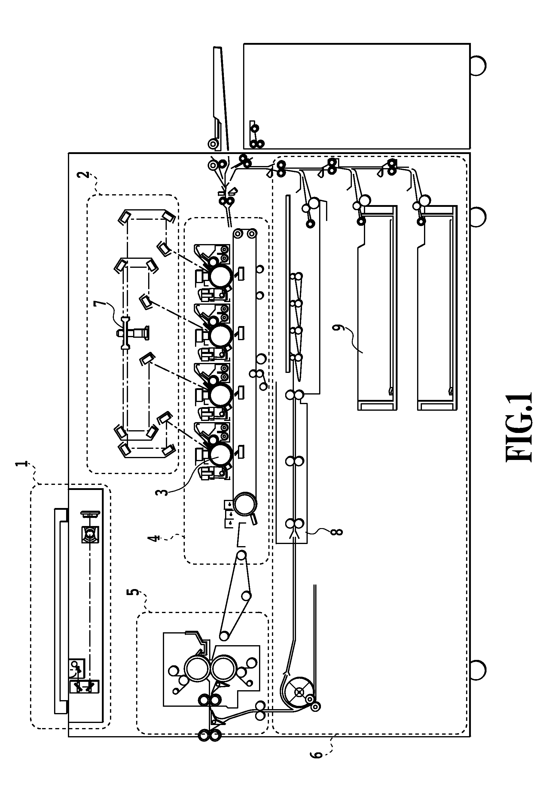
[0036]FIG. 1 is a cross-sectional view illustrating a configuration of a 4D (drums) color system MFP used for the present embodiment.

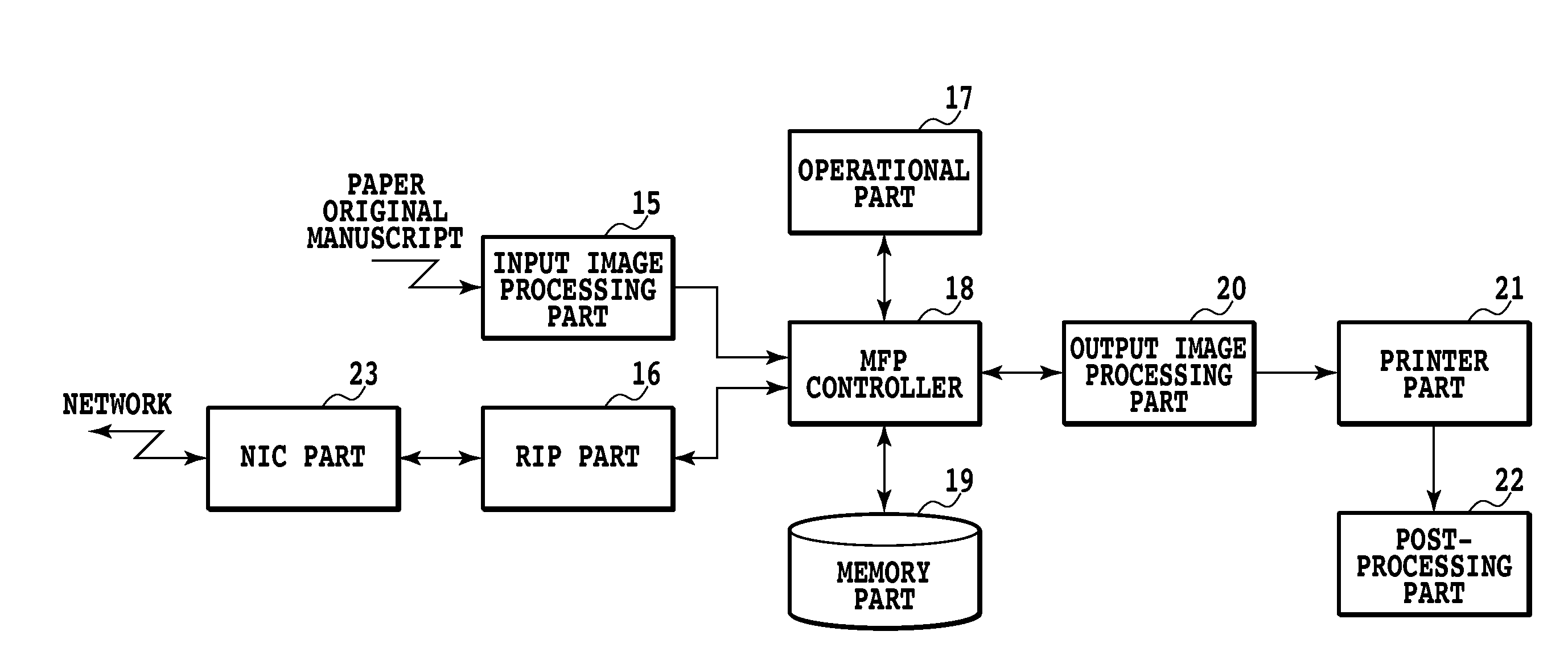
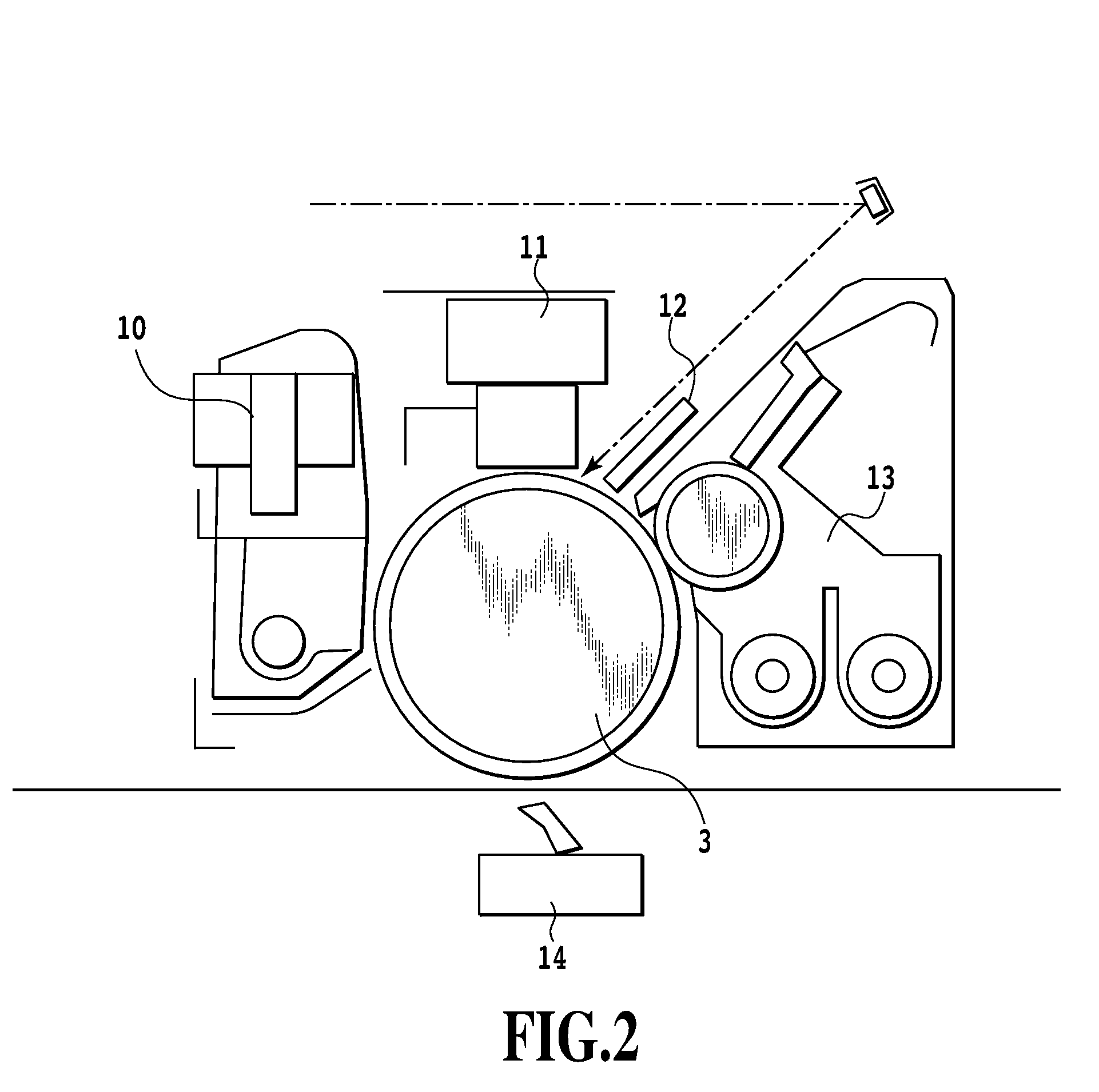
[0037]The 4D color system MFP (four drums system image forming apparatus) is equipped with a scanner part 1, a laser exposing part 2, a photosensitive drum 3, an image forming part 4, a fixing part 5, a feeding / conveying part 6, and a printer controller which controls these parts and is not illustrated in figures.

[0038]The scanner part 1 optically reads an image of an original manuscript, while lightening the original manuscript placed on a manuscript holder, and converts the image into electrical signals to generate image data. The laser exposing part 2 causes light beam such as laser beam, which is modulated depending on the image data to enter a rotating multi-facet mirror (polygon mirror 7) rotating at a constant angular velocity, and illuminate the photosensitive drum 3 as reflected scanning light.

[0039]The image forming part 4 drives the photosen...

second embodiment

[0099]In the present embodiment, instead of a method where as the above mentioned first embodiment, a user intentionally sets with regard to the gradient characteristics near a black point, a method where automatic and optimal correction processing is performed by the type of a profile, setting of gray compensation, and attributes of an input image, will be described. Difference from the first embodiment is in main processing procedures illustrated in FIG. 11, and methods of the correction color conversion table generation processing of FIG. 9 and the other processing are the same as those of the first embodiment.

[0100]FIG. 11 is a main flow chart illustrating the color conversion processing of a color image processing system of the present embodiment. The processing procedure illustrated in FIG. 11 is performed such that CPU 1502 of the host computer 1501 in FIG. 15 mentioned above reads out and executes color profile generation utility program loaded on the memory 1503.

[0101]At St...


PUM


Abstract

The present invention is to provide an image processing system and the method thereof capable of maintaining gradient characteristics near a black point of an output image, when performing color matching in a color printer, even if a source profile has a lower minimum lightness value of output color gamut. In the present invention, when a condition is matched by comparing the minimum lightness points of the source profile and output color gamut, a correction color conversion table is generated by correcting the minimum lightness point of the output color gamut to a correction target value set in advance. Color conversion is performed for an input image using the correction color conversion table.

Description

BACKGROUND OF THE INVENTION[0001]1. Field of the Invention[0002]The present invention relates to a color image processing system and a method thereof, more specifically, it relates to a color image processing system and a method and a program thereof, which relate to a color correction technology for a printer having a color gamut smaller than that of an output machine to be a target.[0003]2. Description of the Related Art[0004]In a color management for an image processing system utilizing various devices, as one of data which plays an important role, there is a color profile. The color profile describes the color reproduction characteristic of the device, and is used in color matching processing for causing the output color of the device to be a desired color. As one of the standards of a general color profile, a profile standardized by ICC (International Color Consortium) is well known, and used normally in color matching processing.[0005]Recently, as an ink-jet system printer and...

Claims


Application Information

Patent Timeline
Patent Type & Authority Applications(United States)
IPC IPC(8): H04N1/60
CPCH04N1/6058
Inventor IDO, YOKO
Owner CANON KK
Learn More