Hologram Recording and Reproducing Apparatus and Hologram Recording Method

a technology of reproducing apparatus and hologram, which is applied in the direction of data recording, recording/reproducing/erasing using optical interference patterns, instruments, etc., can solve the problems of manufacturing cost, and achieve the effect of improving recording density and recording capacity

Inactive Publication Date: 2008-10-09
PIONEER CORP
View PDF15 Cites 7 Cited by
  • Summary
  • Abstract
  • Description
  • Claims
  • Application Information

AI Technical Summary

Benefits of technology

[0007]Accordingly, one of objects that the invention seeks to achieve is to provide a compact hologram recording and reproducing apparatus and a hologr

Problems solved by technology

This will pose a problem from a

Method used


Image

  • Hologram Recording and Reproducing Apparatus and Hologram Recording Method
  • Hologram Recording and Reproducing Apparatus and Hologram Recording Method
  • Hologram Recording and Reproducing Apparatus and Hologram Recording Method

Examples


first embodiment

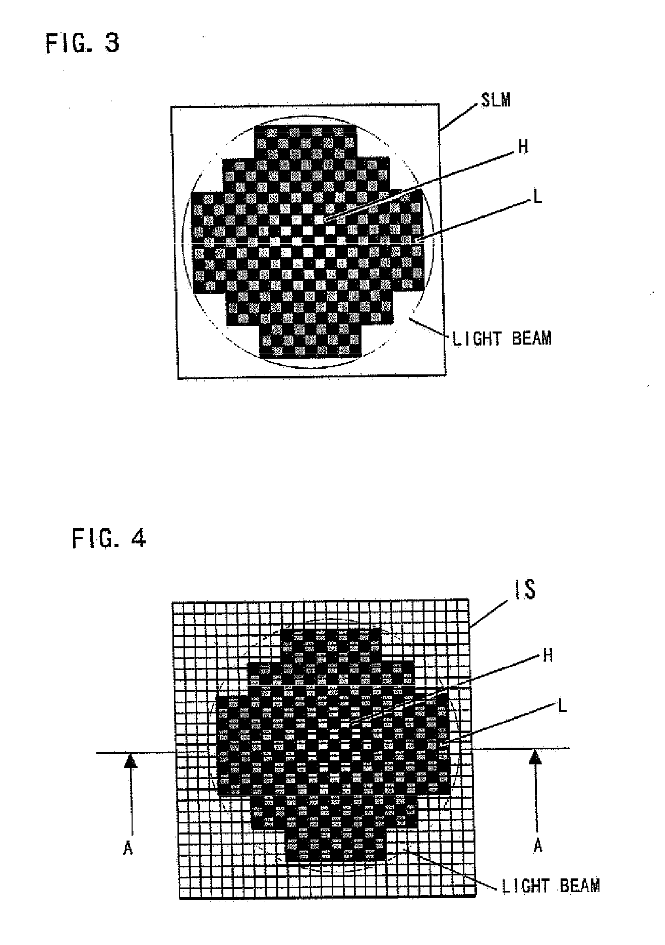
[0051]As shown in FIG. 7, the spatial light modulator SLM is spatially divided into two; a central three-level modulation area HR3 and a surrounding annular two-level modulation area HR2. Thus, as shown in FIGS. 8 and 9, in optically received data based on a reproduced image obtained by focusing the beam that has passed through a Fourier conversion optical system onto the image sensor IS located in a conjugate position, even a non-uniform beam that has passed through the spatial light modulator allows two-level recording (two grayscales of black and white levels) and three-level recording (three grayscales of black, white and gray levels). That is, high multilevel modulation recording is performed only in the multilevel modulation area in the spatial light modulator corresponding to the portion where the contrast of the reproduced image is high, while two-level modulation recording is performed in the modulation area in the spatial light modulator corresponding to the portion where ...

second embodiment

[0053]In addition to the first embodiment in which the multilevel modulation area in the spatial light modulator is fixed in advance, as shown in FIG. 10, the entire spatial light modulator SLM can be configured as a transmissive matrix liquid crystal device in such a way that a spatial light modulator drive circuit 17 displays an annular multilevel modulation area LHR and a central multilevel modulation area HHR therein. That is, the spatial light modulator SLM has a plurality of pixels arranged in a matrix. The control circuit connected to the spatial light modulator SLM spatially classifies the plurality of pixels in the spatial light modulator into the central multilevel modulation area disposed on the optical axis and the annular multilevel modulation area, and delivers signal light for each of the multilevel modulation areas.

[0054]The reproducing operation of the apparatus first begins with initial operation when a recording medium is loaded in the recording and reproducing ap...

third embodiment

[0055]The spatial light modulator shown in FIG. 10 may also be configured in such a way that the control circuit controls the spatial light modulator to define the boundary between the central and annular multilevel modulation areas based on the light intensity distribution detected by the image sensor IS that receives reference light or reproduced light from the hologram area produced by reference light.

[0056]That is, when the contrast distribution of the reproduced image on the image sensor IS is unknown, a test pattern is recorded and reproduced to acquire the contrast distribution, which allows determination of (the boundary of) the multilevel modulation area in the spatial light modulator SLM. The boundary of the multilevel modulation area in the spatial light modulator is determined by a preset contrast threshold value.

[0057]For example, when the contrast distribution varies depending on various recording media, a test pattern is recorded to acquire the contrast distribution. ...


PUM


Abstract

There is provided a hologram recording and reproducing apparatus for a hologram recording medium that stores optical interference fringes therein as a diffraction grating generated by coherent reference light and signal light. The hologram recording and reproducing apparatus includes a control circuit that is connected to a spatial light modulator and controls each pixel in such a way that the reference light is modulated according to information data to produce the signal light. The control circuit spatially classifies a plurality of pixels in the spatial light modulator into a central modulation area disposed on the optical axis and at least one annular modulation area sequentially disposed around the central modulation area in a concentric manner, and controls the pixels in the central modulation area and the pixels in the annular modulation area using respective different recording modulation methods to deliver the signal light through the central modulation area and the annular modulation area.

Description

TECHNICAL FIELD[0001]The present invention relates to a hologram recording and reproducing apparatus that records information by applying signal light through a spatial light modulator onto a hologram recording medium (hereinafter simply referred to as a recording medium), a hologram reproducing apparatus that reproduces information from the recording medium, and a hologram recording method.BACKGROUND ART[0002]For high-density information recording, the hologram technology has attracted attention because of its capability of high-density recording of two-dimensional data. Holograms are characterized in that wavefronts of light carrying information to be recorded are recorded as volumetric variation in refractive index on a recording medium made of a photosensitive material, such as photorefractive material.[0003]For example, there is a known hologram recording apparatus that records data on a recording medium (see JP-A-2004-139021). FIG. 1 is a schematic view showing the hologram re...

Claims


Application Information

Patent Timeline
IPC IPC(8): G11B7/0065G03H1/12
CPCG03H1/12G03H1/26G03H2001/2675G11B7/0065G11B7/083
Inventor OGASAWARA, MASAKAZUITOH, YOSHIHISAKUBOTA, YOSHIHISA
Owner PIONEER CORP
Why Eureka
Try Eureka