Power-maximizing electrical energy generation system

a technology of electrical energy generation and power generation system, which is applied in the direction of secondary cell servicing/maintenance, process and machine control, etc., can solve the problems of inability to maximize the power generated, electrical energy generation system failure to have satisfactory segregation and fault tolerance properties, and it is difficult in such systems to verify reliably that each module is operating correctly. , to achieve the effect of good segregation and fault toleran

Inactive Publication Date: 2008-10-09
EUROPEAN SPACE AGENCY
View PDF8 Cites 49 Cited by
  • Summary
  • Abstract
  • Description
  • Claims
  • Application Information

AI Technical Summary

Benefits of technology

[0014]An object of the invention is therefore to provide an electrical energy generation system comprising a plurality of individual generators enabling maximum power point tracking of said generators combined with satisfactory fault tolerance and / or good segregation between said individual generators.
[0015]Another object of the invention is to provide an electrical energy generation system of this kind that also has good energy efficiency and / or a simple modular structure.
[0016]A further object of the invention is to provide this kind of system enabling modular integration and verification and easy detection of assembly errors.
[0018]wherein said generators are also connected to a common input of an additional DC voltage converter having its output connected to said common load, said additional DC voltage converter also having variable transconductance and said regulator is also configured to vary the transconductance of said additional voltage converter to maximize the power generated by said current generators.
[0033]Said energy storage device may then advantageously be connected to the inputs of said voltage converters, which are adapted to operate as discharge regulators to supply power to said common load from said energy storage device. Said energy storage device may advantageously be connected to the inputs of said respective voltage converters via a third unidirectional device for preventing current flowing from said inputs to said energy storage device.
[0035]According to a second variant of the invention, said common load is an energy storage device connected to supply power to a main power distribution busbar; a secondary power distribution busbar is connected to said common input of the additional DC voltage converter via a voltage regulator; and the input of said input voltage regulator is also connected to said energy storage device via a unidirectional device preventing current flowing from said secondary power distribution busbar to said energy storage device.

Problems solved by technology

This solution has the advantage of simplicity, but cannot maximize the power generated.
Prior art MPPT (maximum power point tracking) electrical energy generation systems do not have satisfactory segregation and fault tolerance properties.
Moreover, it is difficult in such systems to verify reliably that each module is operating correctly after it has been integrated.
However, the fault tolerance of that system is not entirely satisfactory because an isolated fault can cause the loss of an entire section of a solar panel.
However, those regulators do not implement photovoltaic generator maximum power point tracking.

Method used


Image

  • Power-maximizing electrical energy generation system
  • Power-maximizing electrical energy generation system
  • Power-maximizing electrical energy generation system

Examples


first embodiment

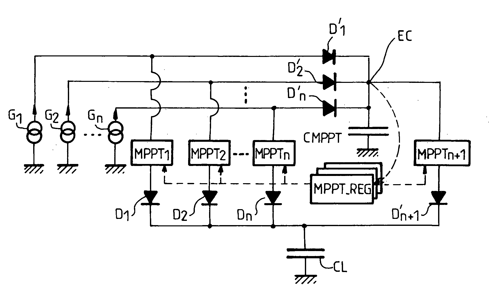
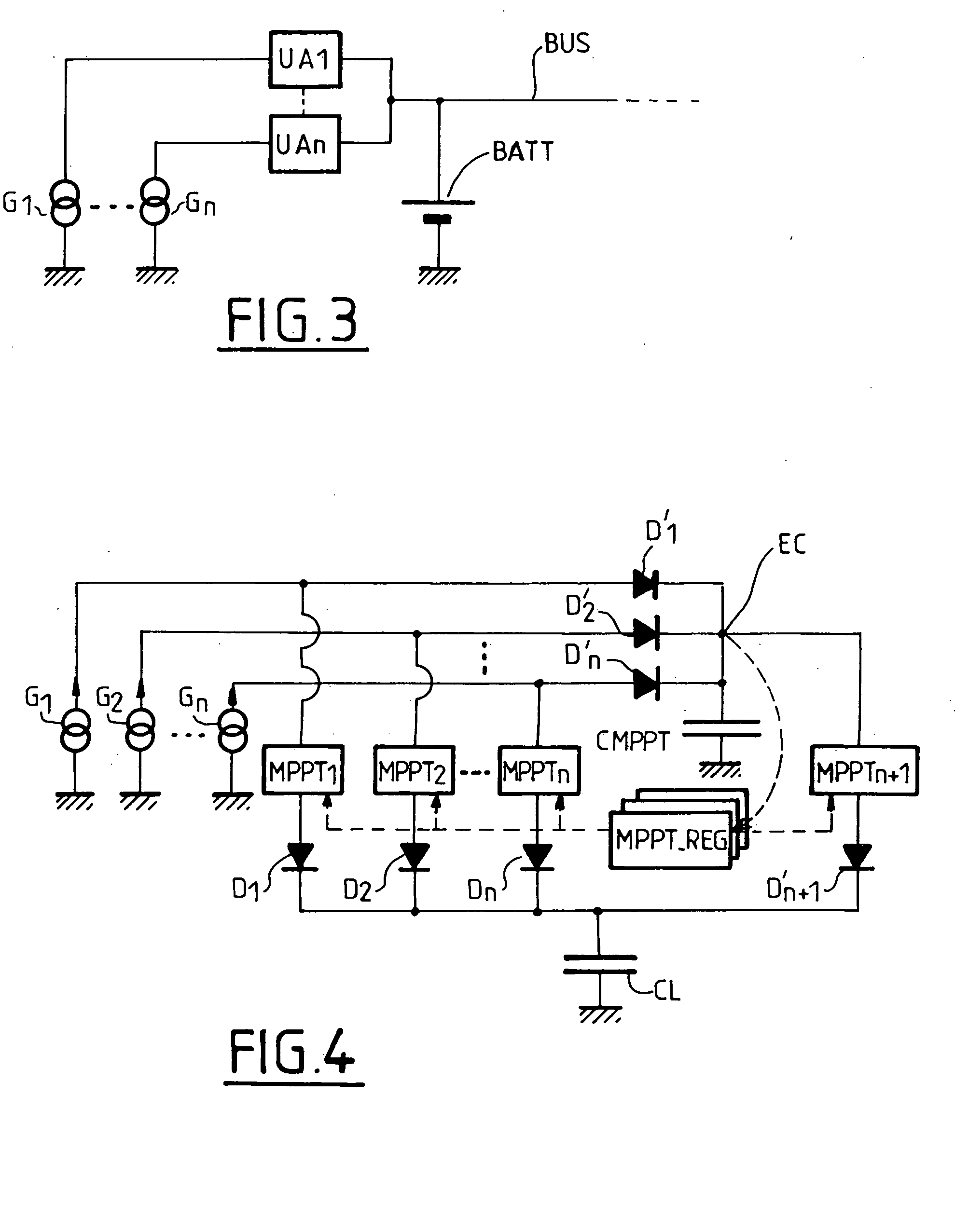
[0055]The topology of an electrical energy system of the invention is represented in FIG. 4.

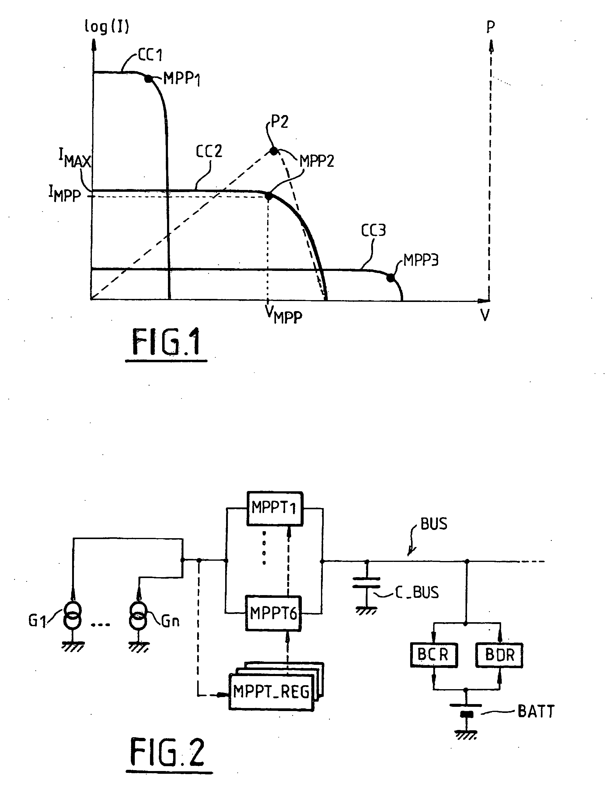
[0056]This system comprises direct current generators G1, G2-Gn, generally photovoltaic generators, connected in parallel and connected to a common load CL via respective voltage converters MPPT1-MPPTn. The common load CL, represented in the figure by a capacitor, can be a regulated or unregulated power distribution busbar or an energy storage device such as a battery.

[0057]The converters can be of the step-down (buck) or step-up type, as a function of the specific application. Their transconductance can be varied by a regulator MPPT_REG in order to operate the generators G1, G2-Gn at their maximum power point. There is one regulator MPPT_REG for all the n voltage converters, as in the Rosetta system. It features majority vote redundancy to provide a reliable regulation signal.

[0058]The maximum power point tracking technique used by the regulator MPPT_REG can advantageously be based on the “p...

third embodiment

[0084]the invention, represented in FIG. 6, is particularly suitable when most of the energy is consumed by a pulsed load, such as a radar or an electrical propulsion system.

[0085]In this embodiment, the photovoltaic generators G1-Gn are connected to charge, via associated voltage converters MPPT1-MPPTn, a battery BATT supplying power to a main power distribution busbar BUS with which the pulsed load L is associated.

[0086]FIG. 6 also includes a secondary power distribution busbar BUS′, also supplying power to the other loads. This secondary power distribution busbar BUS′ is in turn supplied with power by the photovoltaic generators G1-Gn via a voltage regulator REG connected to the point EC. The regulator REG features active redundancy and includes a protection diode D″″ at its output.

[0087]To ensure supply of power to the secondary power distribution busbar BUS′ in an eclipse, the input of said voltage regulator REG is also connected to the battery BATT of the main power distributi...


PUM


Abstract

An electrical energy generation system comprising:a plurality of photovoltaic generators connected in parallel and connected to a common load via respective DC voltage converters; anda regulator configured to vary the transconductances of said respective voltage converters to maximize the power generated by said current generators;wherein:said generators are also connected to a common input of an additional voltage converter the output of which is connected to said common load; andsaid regulator is also configured to vary the transconductance of said additional voltage converter to maximize the power generated by said current generators.

Description

[0001]The invention relates to an electrical energy generation system comprising direct current generators connected in parallel and connected to a common load via respective DC voltage converters, said system further comprising a regulator for varying the transconductances of said voltage converters to maximize the power generated by said current generators.[0002]The invention applies in particular, although this is not limiting on the invention, to photovoltaic solar generators, and more particularly to solar generators of spacecraft.BACKGROUND OF THE INVENTION[0003]Satellites and space probes generally include photovoltaic generators intended to supply power to the onboard equipments and to charge the batteries that supply power during eclipses.[0004]Electrical energy generation systems for space applications are conventionally designed so that the photovoltaic generators operate at a predetermined point on their voltage-current characteristics. This solution has the advantage of...

Claims


Application Information

Patent Timeline
Patent Type & Authority Applications(United States)
IPC IPC(8): H02M3/04
CPCB64G1/443G05F1/67H02J1/12H02J7/345H02J7/35Y10S323/906
Inventor PEROL, PHILIPPE ALFRED
Owner EUROPEAN SPACE AGENCY
Why Eureka
Try Eureka