
Condenser microphone, S/N ratio improvement therefor, and electronic device therefor

a technology of condenser microphone and s/n ratio, which is applied in the direction of piezoelectric/electrostrictive transducers, transducer types, and electrostatic transducers of semiconductor electrostatic transducers, etc., can solve problems such as reducing s/n ratios, and achieve the effect of improving s/n ratio

Inactive Publication Date: 2008-10-09
YAMAHA CORP
View PDF5 Cites 21 Cited by
  • Summary
  • Abstract
  • Description
  • Claims
  • Application Information

AI Technical Summary

Benefits of technology

[0008]It is an object of the present invention to provide a condenser microphone that has an improved S / N ratio.
[0009]It is another object of the present invention to provide a method for improving the S / N ratio of a condenser microphone.
[0010]It is a further object of the present invention to provide an electronic device incorporating a condenser microphone having an improved S / N ratio.

Problems solved by technology

FETs and bias resistors cause thermal noises (or white noises), which reduce S / N ratios.

Method used


Image

  • Condenser microphone, S/N ratio improvement therefor, and electronic device therefor
  • Condenser microphone, S/N ratio improvement therefor, and electronic device therefor
  • Condenser microphone, S/N ratio improvement therefor, and electronic device therefor

Examples


Embodiment Construction

[0050]The present invention will be described in further detail by way of examples with reference to the accompanying drawings.

(A) Microphone Package

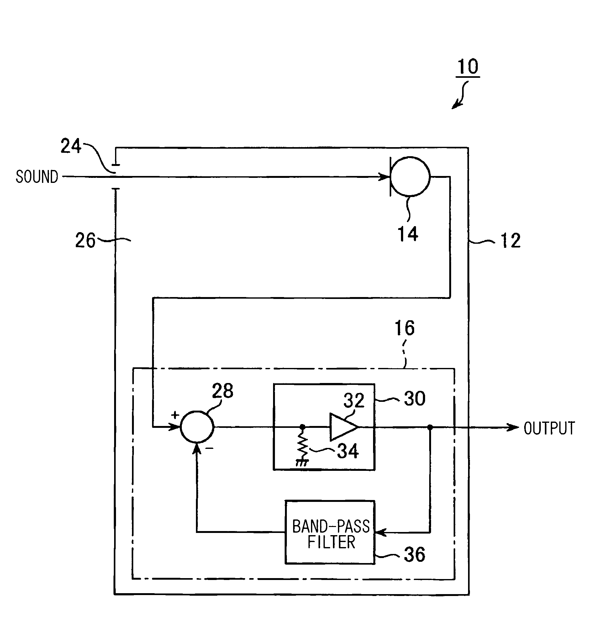
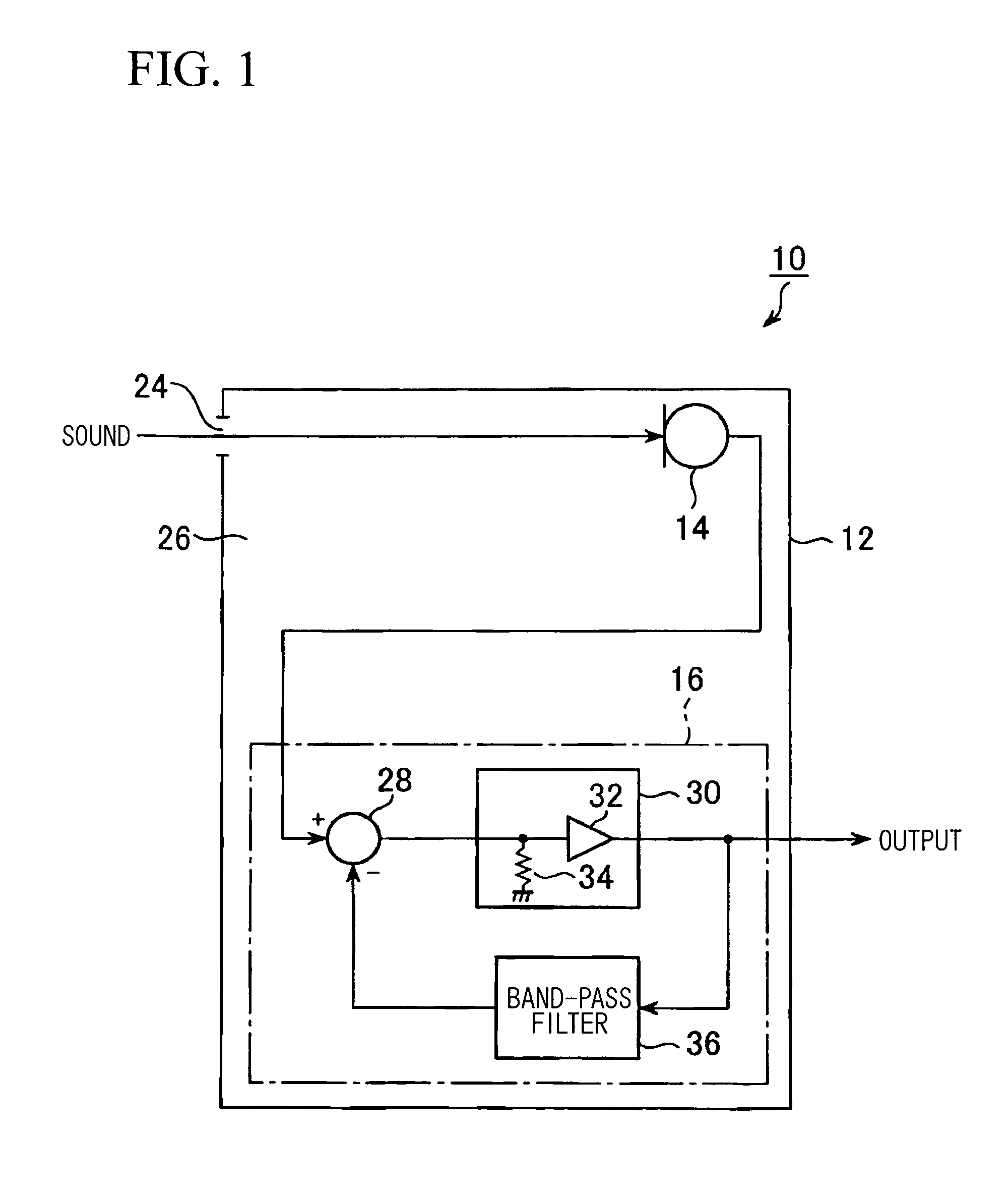
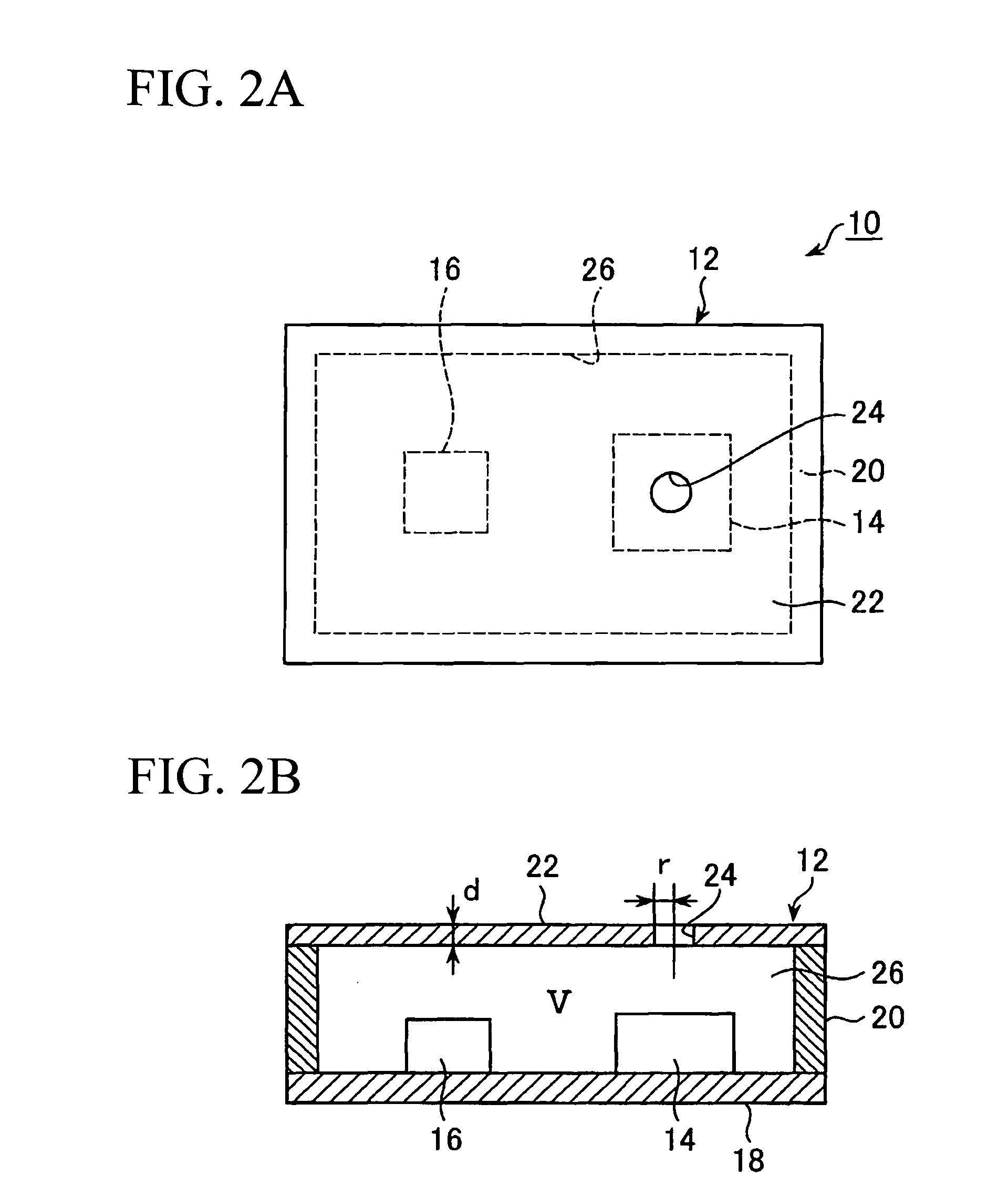
[0051]The mechanical constitution of a silicon microphone 10 will be described with reference to FIGS. 2A and 2B. FIG. 2A is a plan view of the silicon microphone 10, and FIG. 2B is a longitudinal sectional view showing the internal structure of the silicon microphone 10. The silicon microphone 10 includes a microphone chip (or an MEMS chip) 14 and an LSI chip 16, which are encapsulated in a microphone package 12. The microphone package 12 is constituted of a bottom 18 (i.e., a substrate having printed circuitry), side walls 20 composed of metals, and a cover 22 composed of a thin metal plate. The microphone chip 14 and the LSI chip 16 are fixed onto the surface of the substrate 18. A sound hole 24 having a circular shape is opened at a prescribed position of the cover 22. External sound enters via the sound hole 24 so as to propagate t...


PUM


Abstract

A condenser microphone includes a microphone chip and an LSI chip, which are stored in a microphone package having a sound hole. External sound enters the sound hole so as to propagate through the internal space of the microphone package, so that it is received by the microphone chip. The microphone package is designed to set the Helmholtz resonance frequency within the audio frequency range. The output signal of the microphone chip is supplied to an impedance converter included in the LSI chip. The output signal of the impedance converter is attenuated by an attenuation device with respect to the prescribed frequency band including the Helmholtz resonance frequency, which decreases when the condenser microphone is installed in the housing of an electronic device. Thus, it is possible to achieve the flat frequency characteristics in the output signal of the condenser microphone, which is thus improved in the S / N ratio.

Description

BACKGROUND OF THE INVENTION[0001]1. Field of the Invention[0002]The present invention relates to condenser microphones such as electret condenser microphones and to improvements of the S / N ratios of condenser microphones. The present invention also relates to electronic devices incorporating condenser microphones.[0003]The present application claims priority on Japanese Patent Application No. 2007-99683, the content of which is incorporated herein by reference.[0004]2. Description of the Related Art[0005]It is required that microphones incorporated into cellular phones be reduced in size and weight. To cope with such requirement, silicon microphones (or MEMS microphones, wherein MEMS stands for Micro Electro Mechanical System), which are condenser microphones manufactured based on the MEMS technology, have been developed and installed in electronic devices.[0006]Non-Patent Document 1: “Microphone Handbook”, Vol. 1, Bruel & Kjaer, pp. 4-8 to 4-11.[0007]Condenser microphones have high...

Claims


Application Information

Patent Timeline
IPC IPC(8): H04R11/04
CPCH04R1/2838H04R19/005H04R19/016H04R19/04H04R2499/11
Inventor SATO, AKIYOSHI
Owner YAMAHA CORP
Learn More