Component for Machine Structure, Method of Producing the Same and Material for Induction Hardening

a machine structure and component technology, applied in the direction of increasing energy efficiency and improving process efficiency, can solve the problems of insufficient satisfaction of the demand for fatigue strength, poor productivity, saturated fatigue strength at a certain depth, etc., and achieve excellent fatigue properties

Inactive Publication Date: 2008-10-09
JFE STEEL CORP
View PDF0 Cites 19 Cited by
  • Summary
  • Abstract
  • Description
  • Claims
  • Application Information

AI Technical Summary

Benefits of technology

[0040]According to the invention, there can be stably obtained components for machine structure having excellent fatigue properties exemplifying torsional fatig...

Problems solved by technology

However, the fatigue strength is saturated at a certain depth even in the increase of the hardening depth.
For this end, it is required to raise the heating temperature in the hot rolling, so that there is a problem that the productivity is poor.
Also, there is still a problem that the recent demand on the fatigue strengths is not sufficiently...

Method used


Image

  • Component for Machine Structure, Method of Producing the Same and Material for Induction Hardening
  • Component for Machine Structure, Method of Producing the Same and Material for Induction Hardening
  • Component for Machine Structure, Method of Producing the Same and Material for Induction Hardening

Examples


example 1

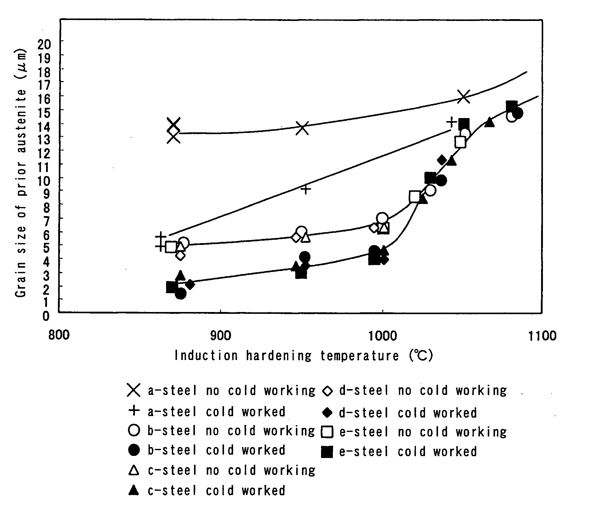
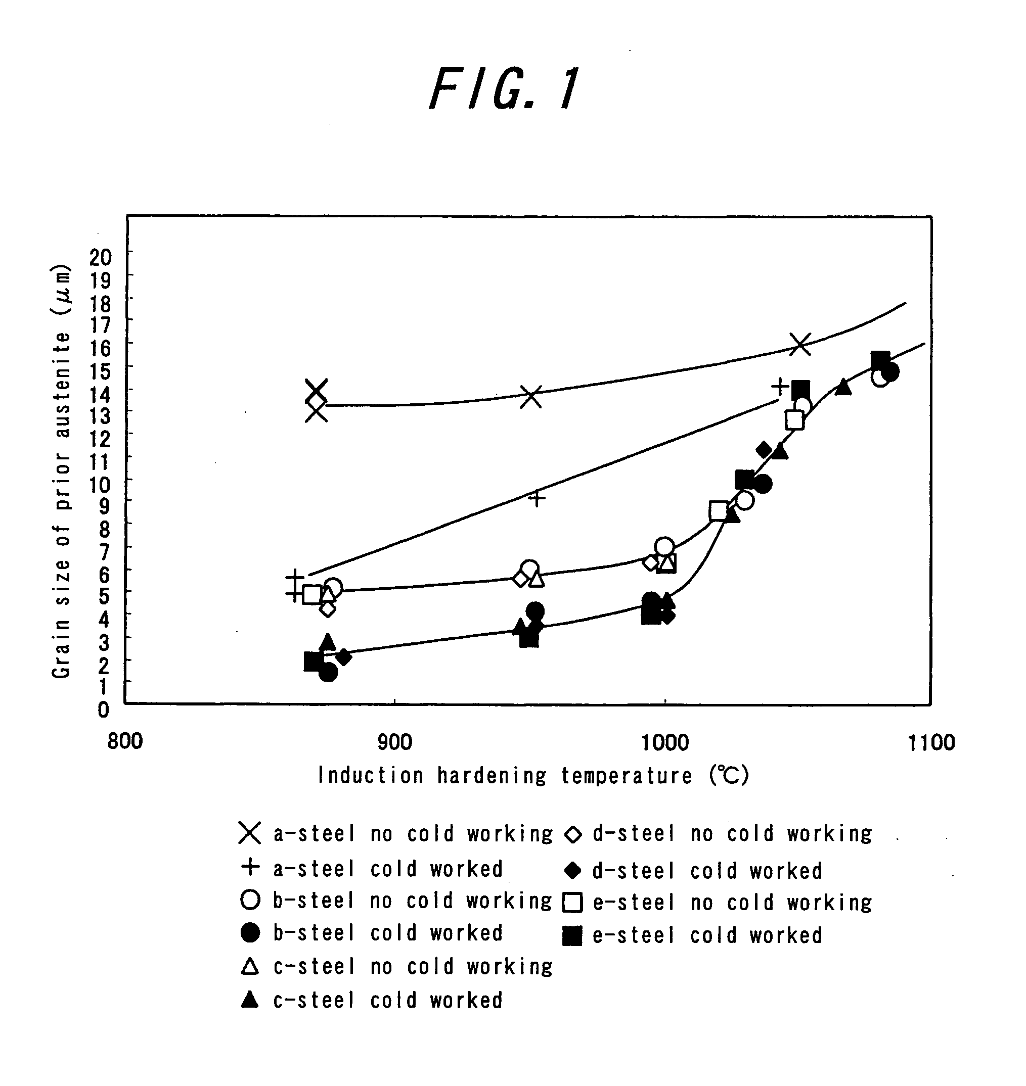
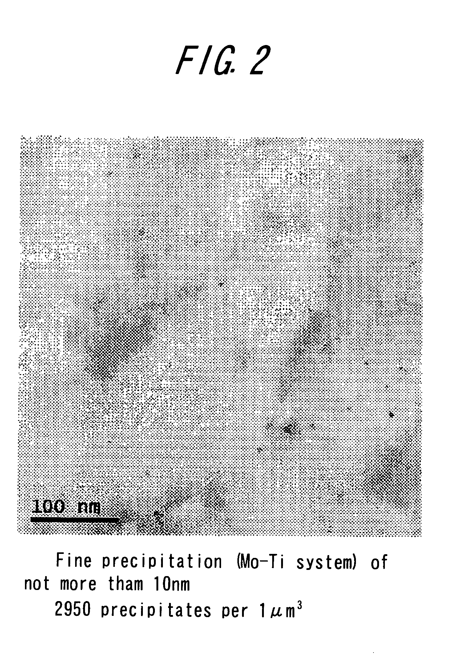
[0166]100 kg of a steel shown in Table 1 is melted and heated to 1200° C. and shaped into a sample for torsional fatigue test under hot working conditions and cold working conditions shown in Table 2. The shaped sample is first subjected to an induction hardening at 1050° C. and subsequently to an induction hardening under conditions shown in Table 2. Moreover, the induction hardening at 1050° C. is not carried out in Test No. 10. Also, in the tests other than Test Nos. 29 and 30, the tempering of 160° C.×1 h. is carried out after the induction hardening. The grain size of prior austenite and hardness in the induction hardened portion are measured in the same method as mentioned above. In the torsional fatigue test, stress broken at torsion number of 105 is measured on the torsional stepped test specimen of 18 mmφ. Also, the microstructure prior to the induction hardening is observed by means of an optical microscope to identify the microstructure, and at the same time the microstru...

example 2

[0168]As a component for machine structure according to the invention is prepared a constant velocity joint 12 interposed for transmitting a motive energy from a drive shaft 10 to a wheel hub 11 as shown in FIG. 5.

[0169]The constant velocity joint 12 is a combination of an outer wheel 13 sand an inner wheel 14. That is, the inner wheel 14 is swingably fixed to an inside of a mouth portion 13a of the outer wheel 13 through balls 15 fitted into a ball track groove formed in the inner face of the mouth portion 13a, while the drive shaft 10 is connected to the inner wheel 14. A stem portion 13b of the outer wheel 13 is, for example, spline-bonded to the hub 11, whereby the motive energy is transmitted from the drive shaft 10 to the hub 11 of the wheel.

[0170]A starting material of steel having a chemical composition shown in Table 3 is melted in a converter and continuously cast to form a cast bloom. The cast bloom has a size of 300×400 mm. The cast bloom is rolled into a billet of 150 m...


PUM

PropertyMeasurementUnit
Grain sizeaaaaaaaaaa
Temperatureaaaaaaaaaa
Percent by massaaaaaaaaaa

Abstract

There is provided a component for machine structure having a hardened layer through an induction hardening in at least a part thereof, and more improving fatigue strengths as compared with the conventional ones, in which the hardened layer has a hardness Hv of not less than 750 and an average grain size of prior austenite grains is not more than 7 μm over a full thickness of the hardened layer.

Description

TECHNICAL FIELD[0001]This invention relates to a component for machine structure provided in at least a part thereof with a hardened layer through an induction hardening. As the component for machine structure may be mentioned a drive shaft for an automobile, an input shaft, an output shaft, a crankshaft, inner and outer wheels of a constant velocity joint, a hub, a gear and so on.RELATED ART[0002]Heretofore, in the components for machine structure such as a drive shaft for an automobile, a constant velocity joint and the like, it is usual to ensure fatigue strengths as a characteristic of the component for machine structure such as torsional fatigue strength, bending fatigue strength, rolling fatigue strength, slip rolling fatigue strength and the like by working a hot rolled steel bar into a given shape through hot forging, cutting, cold forging and the like and then subjecting to induction hardening and tempering.[0003]On the other hand, it is strongly demanded to reduce the weig...

Claims


Application Information

Patent Timeline
IPC IPC(8): C22C38/00C21D1/42C22C38/20
CPCC21D1/10C22C38/001C22C38/002C22C38/02C22C38/04C22C38/12C22C38/14C22C38/60Y02P10/25
Inventor HAYASHI, TORUOHMORI, YASUHIROKUROSAWA, NOBUTAKAMATSUZAKI, AKIHIROTOYOOKA, TAKAAKIYAMADA, KATSUMI
Owner JFE STEEL CORP
Why Eureka
Try Eureka