Hydrogen Tank Cooling Device and Cooling Method in Hydrogen Fuel Automobile, and Hydrogen Fuel Automobile

a hydrogen fuel automobile and cooling device technology, which is applied in the direction of secondary cells, vessel geometry/arrangement/size, vessel mounting details, etc., can solve the problems affecting the cooling effect of the hydrogen tank, and affecting the cooling effect of the general radiator and fan for automobile use. , to achieve the effect of shortening the time for filling the hydrogen tank

Inactive Publication Date: 2008-10-16
TOYOTA IND CORP +1
View PDF7 Cites 27 Cited by
  • Summary
  • Abstract
  • Description
  • Claims
  • Application Information

AI Technical Summary

Benefits of technology

[0013]An objective of the present invention is to provide a hydrogen tank cooling device in a hydrogen fuel automobile which can make the time for filling the tank with hydrogen short in comparison with a case where the hydrogen tank is cooled using the radiator and the fan mounted in the automobile when the tank is filled with hydrogen. Furthermore, the present invention provides a hydrogen tank cooling method and a hydrogen fuel automobile.
[0015]The present invention further provides a hydrogen tank cooling method used when a hydrogen tank mounted in a hydrogen fuel automobile is filled with hydrogen. The hydrogen fuel automobile is provided with a heat medium passage through which a heat medium for cooling the hydrogen tank flows, a radiator for cooling the heat medium that flows through the heat medium passage, and an air cooling apparatus. The cooling method includes the steps of driving a fan in order to blow wind against the radiator and driving the air cooling apparatus when the hydrogen tank is being filled with hydrogen, and aiding cooling of the hydrogen tank by the refrigerant in the air cooling apparatus.

Problems solved by technology

While the hydrogen tank is being filled with hydrogen gas, the temperature inside the hydrogen tank becomes high, and therefore, it takes time to fill the hydrogen tank with hydrogen gas, unless the hydrogen tank is filled with hydrogen gas while being cooled.
In addition, in the case where the amount of hydrogen with which the hydrogen tank is filled is increased by making a hydrogen storage alloy store hydrogen, the hydrogen storage reaction in the hydrogen storage alloy is an exothermal reaction, and therefore, the hydrogen storage reaction does not progress smoothly, unless the hydrogen tank is cooled.
However, in the case where the hydrogen storage alloy stores hydrogen, that is to say, when the hydrogen tank is being filled with a large amount (for example, 5 kg) of hydrogen in a short period of time (for example, within 5 minutes) under high pressure (for example, 35 MPa), general radiators and fans for automobile use lack the ability to release heat generated in the hydrogen storage alloy and heat resulting from gas compression to the outside.
In the case where a fan which can provide this wind velocity is mounted in a fuel cell automobile, however, a large space for installation becomes necessary, and the fuel cell automobile ends up being equipped with a fan of which the performance is excessive at all times except when the tank is being filled with hydrogen.

Method used


Image

  • Hydrogen Tank Cooling Device and Cooling Method in Hydrogen Fuel Automobile, and Hydrogen Fuel Automobile
  • Hydrogen Tank Cooling Device and Cooling Method in Hydrogen Fuel Automobile, and Hydrogen Fuel Automobile
  • Hydrogen Tank Cooling Device and Cooling Method in Hydrogen Fuel Automobile, and Hydrogen Fuel Automobile

Examples


first embodiment

[0024]In the following, the present invention will be described.

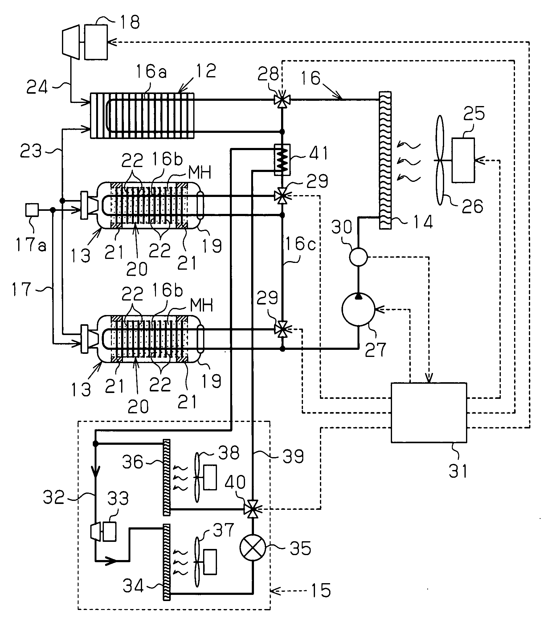
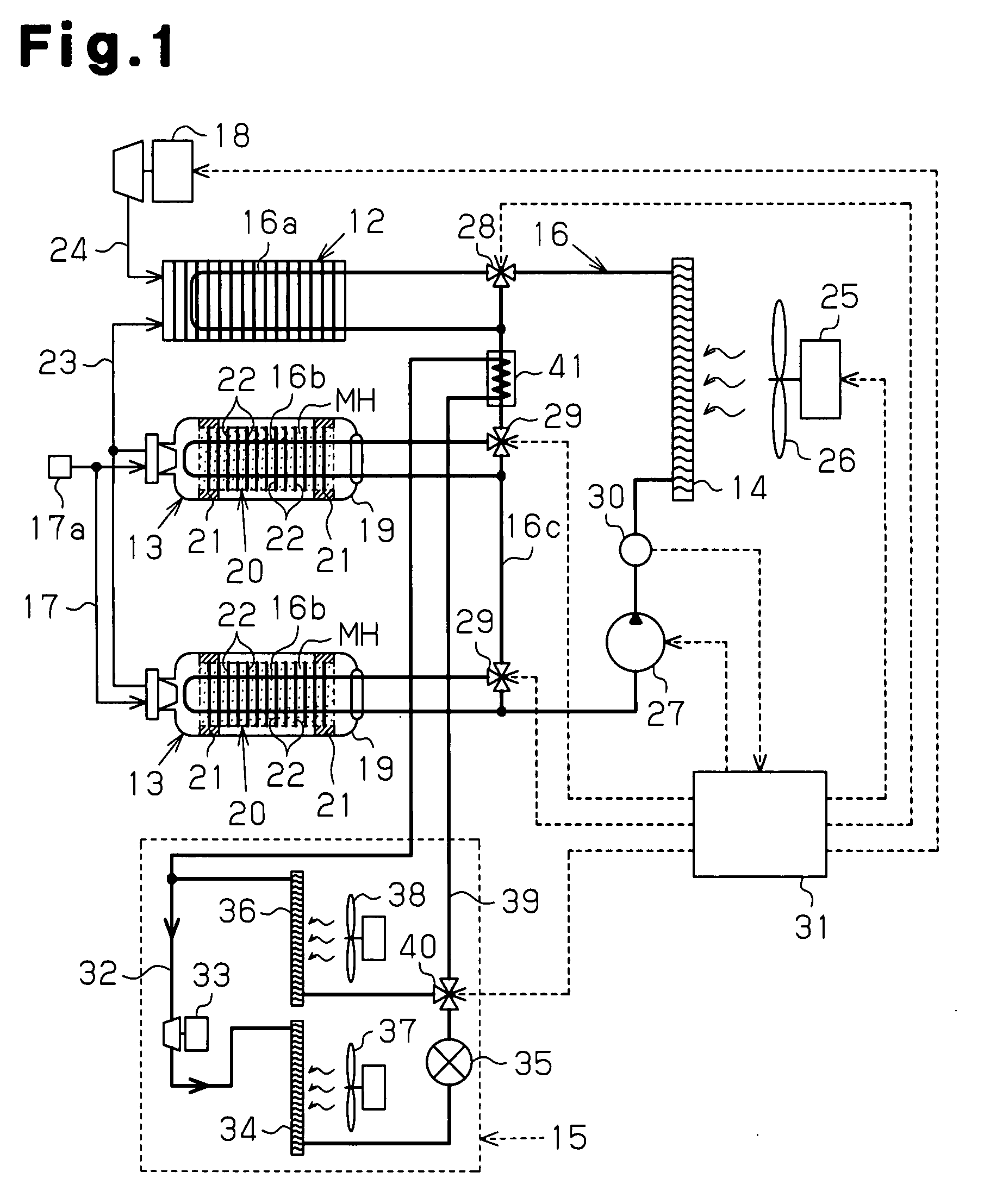
[0025]As shown in FIG. 2, a hydrogen fuel automobile 11 is provided with a fuel cell 12 as a hydrogen fuel drive portion for driving the vehicle, two hydrogen tanks 13, a radiator 14 and an air cooling apparatus 15. The fuel cell 12, the hydrogen tanks 13, and the radiator 14 are linked via a heat medium passage 16 which makes it possible to supply a heat medium for cooling the fuel cell 12 to the hydrogen tanks 13. The hydrogen tanks 13 are linked to a pipe 17 having an opening for filling the tanks 13 with hydrogen filling port 17a. It is possible to fill the respective hydrogen tanks 13 with a hydrogen gas through the pipe 17.

[0026]In addition, the hydrogen fuel automobile 11 is formed in such a manner that the hydrogen tanks 13 can be filled with hydrogen gas at a hydrogen station 51. The hydrogen station 51 is provided with a gas storing installation 52 for storing hydrogen gas and a dispenser 53 for filling the hy...

second embodiment

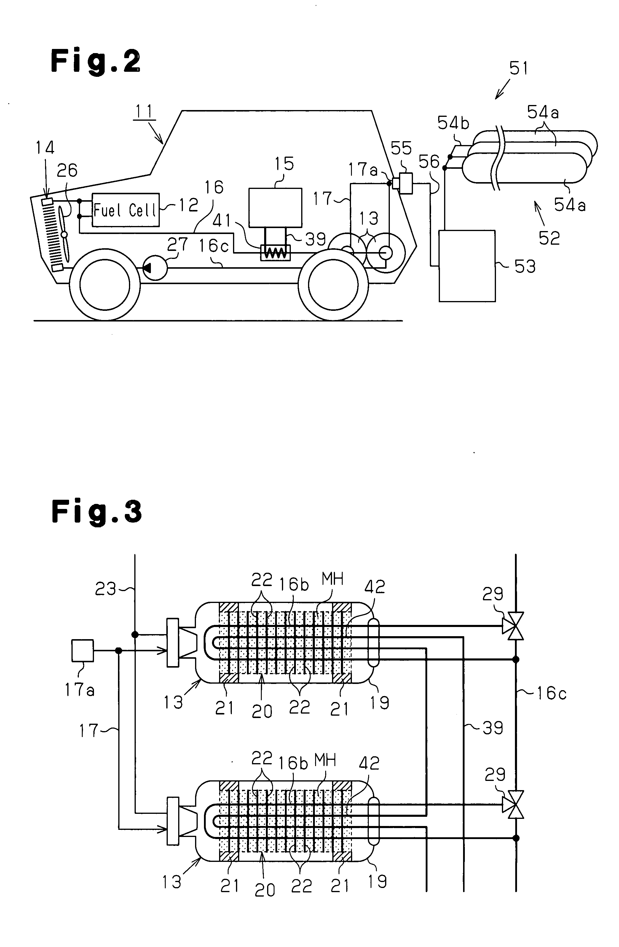
[0063]The refrigerant pipe 42 for causing the refrigerant liquid that flows through the bypass passage 39 to flow into the hydrogen tank 13 does not need have such a configuration as to be completely independent of the second heat exchanging portion 16b as in the second embodiment, but may be configured such that the second heat exchanging portion 16b and the refrigerant pipe 42 are provided as a double pipe. As shown in FIGS. 4A and 4B, for example, a double pipe having a configuration where a refrigerant pipe 42 in U shape having a small diameter is inserted into a pipe in U shape which serves as the second heat exchanging portion 16b is used. The inlet portion 42a and the outlet portion 42b of the refrigerant pipe 42 are formed so as to extend through the pipe wall of the second heat exchanging portion 16b in such a state as to cross the U shaped pipe of the refrigerant pipe 42 at the end portions in such a manner as to be perpendicular to the U shaped pipe. In addition, bypass p...


PUM


Abstract

A hydrogen fuel automobile has a heat medium passage through which a heat medium which can exchange heat with a drive portion and can be supplied to a heat medium pipe for a hydrogen tank flows. An air cooling apparatus has a compressor for compressing a refrigerant gas, a condenser, an evaporator and a refrigerant circuit. The hydrogen fuel automobile is provided with a bypass passage which branches from the refrigerant circuit so that expanded refrigerant liquid detours the evaporator so as to be drawn into the compressor. A switch portion can switch between a state where the refrigerant liquid passes through the evaporator so as to be drawn into the compressor and a state where the refrigerant liquid detours the evaporator so as to flow through the bypass passage. The hydrogen storage material cooling portion cools the hydrogen storage material in the hydrogen tank using the refrigerant liquid that flows through the bypass passage. Accordingly, the time for filling the tank with hydrogen can be made short in comparison with a case where the radiator and the fan mounted in the automobile are used to cool the hydrogen tank when the tank is being filled with hydrogen.

Description

TECHNICAL FIELD[0001]The present invention relates to a hydrogen tank cooling device and cooling method in a hydrogen fuel automobile, and a hydrogen fuel automobile. In particular, the present invention relates to a technology for allowing a hydrogen tank to be filled with hydrogen in a short period of time in comparison with the prior art in a hydrogen fuel automobile in which a hydrogen tank having a hydrogen storage material inside and an air cooling apparatus are mounted.BACKGROUND ART[0002]In recent years, awareness in terms of the need to control global warming has been rising, and in particular, hydrogen fuel automobiles using hydrogen as fuel, such as fuel cell electric automobiles and hydrogen engine automobiles, have been actively developed for the purpose of reducing carbon dioxide discharged from vehicles. A hydrogen tank which is filled with hydrogen gas is mounted as a hydrogen supply source in general hydrogen fuel automobiles.[0003]In methods for storing and transpo...

Claims


Application Information

Patent Timeline
Patent Type & Authority Applications(United States)
IPC IPC(8): B60H1/32F25B1/00B60H3/00F28D15/00
CPCB60K2001/005B60K2015/03414F17C5/007F17C11/005F17C13/025F17C2201/0104F17C2205/0142F17C2221/012F17C2223/0123F17C2223/036F17C2225/0123F17C2225/036F17C2250/03F17C2250/032F17C2250/043F17C2250/0443F17C2265/066F17C2270/0139F17C2270/0178F17C2270/0184F28D7/106F28D7/14F28D2021/0047H01M8/04208H01M2250/20Y02E60/321Y02T90/32Y02E60/50Y02E60/32Y02T90/40
Inventor KUBO, HIDEHITOMORI, DAIGORO
Owner TOYOTA IND CORP
Why Eureka
Try Eureka