
Separation devices and processes

a separation device and process technology, applied in the direction of membranes, separation processes, filtration separation, etc., can solve the problems of increased power required to maintain the flow through the membrane, increase the cost of the separation process, and shift in the cut-off size, so as to achieve enhanced permeation throughput, high shear rate, and high efficiency of use of the entire porous medium

Inactive Publication Date: 2008-10-16
PALL CORP
View PDF11 Cites 31 Cited by
  • Summary
  • Abstract
  • Description
  • Claims
  • Application Information

AI Technical Summary

Benefits of technology

The present invention provides improved separation devices and processes. These devices and processes operate at higher shear rates, which allows them to operate for longer periods of time without fouling the porous medium and forming a gel layer. Additionally, these devices provide control of the permeate flow and pressure, resulting in more efficient use of the porous medium and enhanced permeate throughput even at higher shear rates.

Problems solved by technology

This results in an increase in the power required to maintain the flow through the membrane and a shift in the cut-off size.
Both of these results of fouling have important consequences for separation processes.
The increase in power required increases the cost of the separation process and the shift in cut-off size affects the function of the separation processes.
In many separation applications, especially those involving biological fluids, the shift in cut-off size renders the use of conventional dead-end filters ineffective.
Although effective, conventional cross-flow separation is not without serious problems.
One problem is non-uniform distribution of the flow over the membrane surface, especially with cross-flow devices that are made up of flat sheets of membranes with wide rectangular channels for the feed flow.
Another problem, which affects both tubular and rectangular channel forms of conventional cross-flow devices, is that the shear rates generated in conventional cross-flow devices are frequently not large enough to prevent the development of a layer of highly concentrated suspended particles on the feed (or upstream) side of the membrane.
As a result, many conventional cross flow devices and processes are unable to effect separations of particles that differ in size by less than an order of magnitude.
However, it has generally been considered impractical to substantially increase the shear rate because a large pressure gradient from the feed inlet to the retentate outlet causes a large permeate flux at the inlet end of the device and a relatively small permeate flux at the retentate end.
The large flux near the inlet counteracts the shear and leads to concentration polarization, while the small flux at the outlet reduces throughput and efficient use of the membrane.
Restricting the permeate flow by means of a control valve downstream of the permeate outlet does not alleviate this problem.
However, the rate of fouling increases with flux; so the relationship between permeate flux and TMP is not generally linear.
This approach, which is described in U.S. Pat. No. 4,105,547, requires the added expense of a pump to drive the re-circulating permeate flow.
Another difficulty with re-circulating permeate to maintain uniform TMP is that generally the permeate volume flow rate is so much smaller than the retentate flow rate that the re-circulation rate must be very large, or the cross sectional area of the permeate passages must be excessively small, to establish a pressure drop equal to that on the retentate side.

Method used


Image

  • Separation devices and processes
  • Separation devices and processes
  • Separation devices and processes

Examples


example

[0057]The cross flow device 30 shown in FIGS. 3 and 4 and the previously described test setup incorporating the cross flow device 30 were used to filter raw skim milk (0.08% milk fat) at 127° F. The target pressure drop PG along the gap 44 was 20 psi to produce a shear rate of 7×10⁵ inverse seconds.

[0058]Prior to initiating the test run, conditions were set to prevent Starling flow reverse pressure rupture of the membrane and to prevent premature fouling of the membrane. The target feed milk flow rate was established in a bypass-to-drain upstream of the test fixture, at the target flow rate, pressure and temperature. The test fixture was prewarmed with water and the retentate valve was set to produce half the target pressure drop PG. Then the feed milk pressure was reduced to half PG; water flow to the test fixture was stopped; and milk flow was diverted into the test fixture. The permeate valve was opened very slightly to allow minor permeate flow, reducing the permeate pressure an...


PUM

PropertyMeasurementUnit
widthaaaaaaaaaa
heightaaaaaaaaaa
widthsaaaaaaaaaa

Abstract

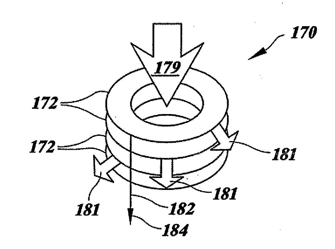
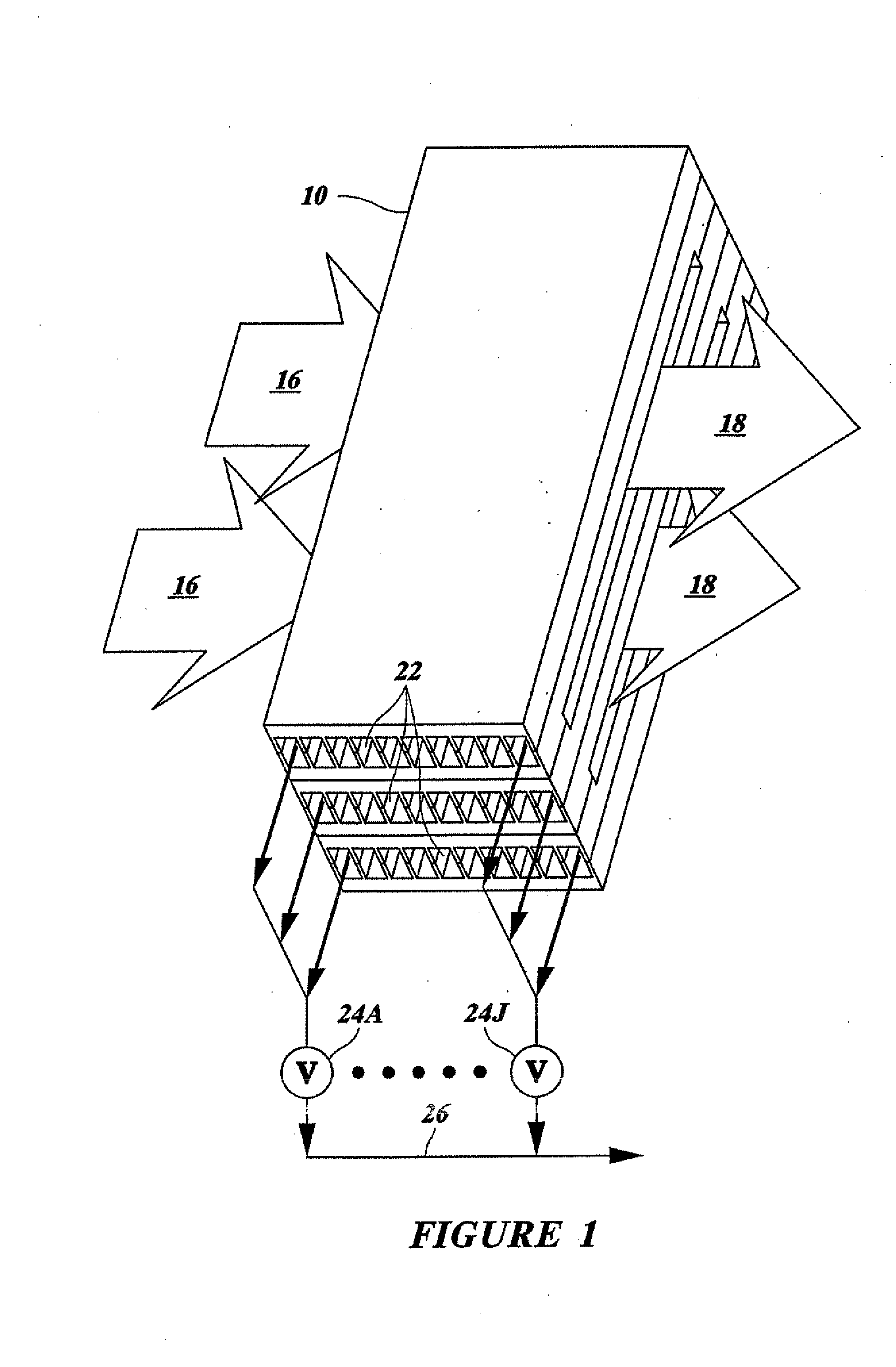
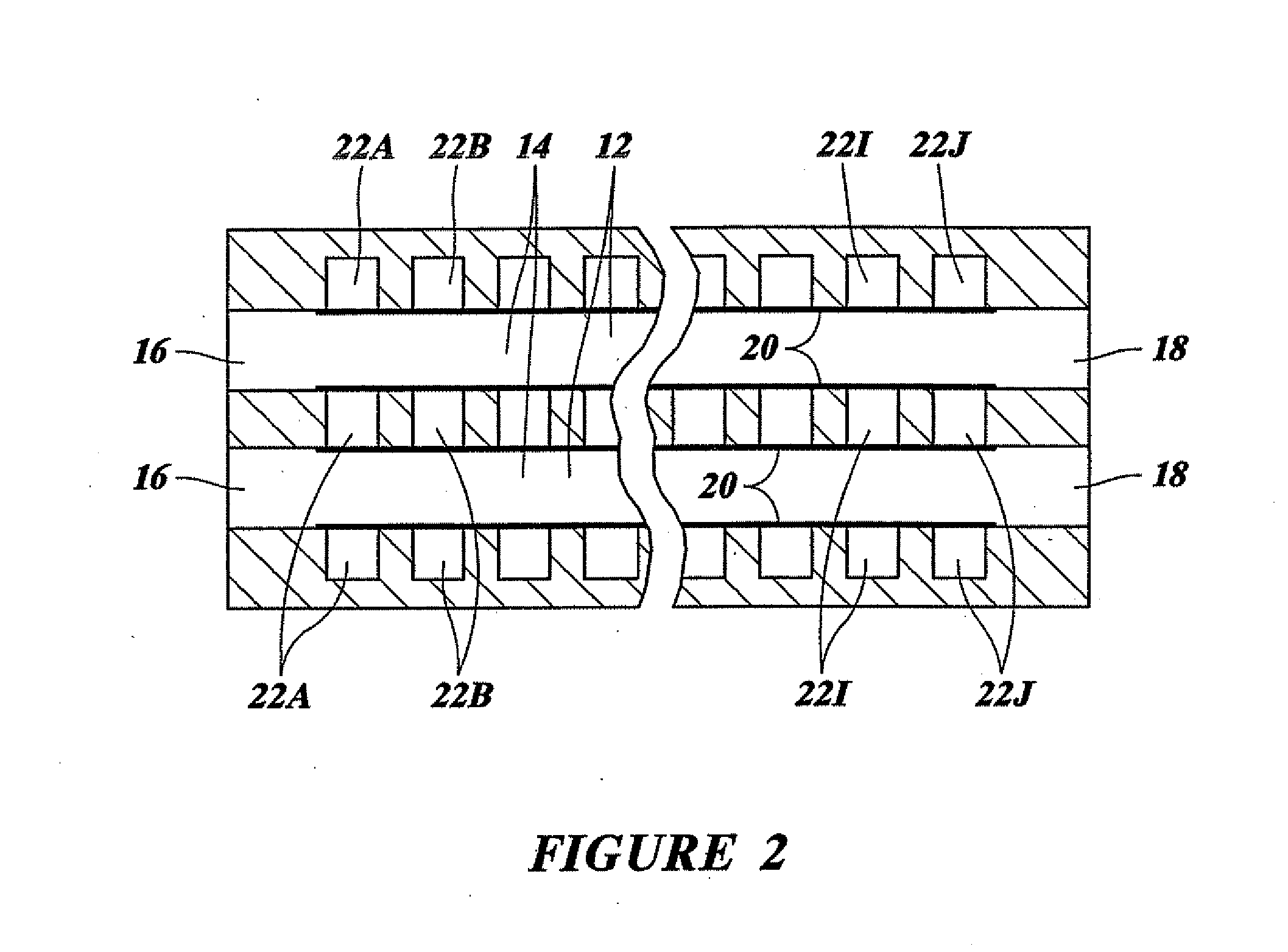
A separation device comprises a cylindrical separation pack including a spirally wound porous medium, a feed channel including a shear region, a plurality of permeate passages extending along the permeate side of the porous medium opposite the shear region and perpendicular to the feed channel, a feed inlet, a retentate outlet, and a plurality of permeate outlets.

Description

[0001]This application claims priority of U.S. Application No. 60 / 117,972, which is incorporated by reference.FIELD OF THE INVENTION[0002]This invention relates to the separation of particles and / or fluid from a mixture including the particles suspended in the fluid. For example, it relates to the purification or clarification of a fluid by removing particles from the fluid; to the segregation of particles by removing one or more types, sizes, or species of particles from the fluid; and to the concentration of one or more types, sizes, or species of particles by the removal of a portion of the fluid.[0003]The invention is useful for a wide variety of particles and fluids in microfiltration, ultrafiltration, nanofiltration, reverse osmosis, and shear separation as described, for example, in International Publication No. WO98 / 09717. For example, the particles could be macro-molecules, micelles, liposomes, or bacteria suspended in a fluid, such as a biological fluid, as would be common...

Claims


Application Information

Patent Timeline
Patent Type & Authority Applications(United States)
IPC IPC(8): B01D29/23
CPCA23C9/1422B01D61/12B01D61/22B01D63/066B01D63/082B01D63/084B01D63/10B01D65/08B01D2311/14B01D2311/16B01D2315/10B01D2321/2008
Inventor FENDYA, THOMAS J.HURWITZ, MARK F.MILLER, JOHN D.GEIBEL, STEPHEN A.SAMSON, MARC
Owner PALL CORP
Learn More