Embossing Device with a Deflection Compensated Roller

a deflection compensation and embossing technology, which is applied in the direction of mechanical work/deformation, manufacturing tools, other domestic objects, etc., can solve the problems of unnecessarily compressing the substratum at the end areas of the rolls, and achieve the effect of reducing the mass of the rolls

Inactive Publication Date: 2008-10-16
AVANTONE OY
View PDF14 Cites 11 Cited by
  • Summary
  • Abstract
  • Description
  • Claims
  • Application Information

AI Technical Summary

Benefits of technology

[0008]The main object of the present invention is to enable the production of a diffractive microstructure having an even pattern depth into a wide substrate. Another object of the present invention is to enable the use of slim rolls and to reduce the mass of the rolls.
[0015]The diameters of the rolls of the embossing device according to the invention do not have to be large and the rolls may be constructed such that their mass is moderate. If desired, the compressible coating of the backing roll may be selected to be very hard and thin, or it may even be omitted. This is advantageous for example in that respect that the tendency of the coating to spread sideways under the effect of the embossing pressure is reduced, and thus, the displacement of the substrate in the direction of the surface is minimized when producing the microstructure. Said displacement may degrade the produced microstructure.
[0016]By means of the embossing device according to the present invention, it is possible to produce diffractive microstructures with even pattern depths especially on wide substrates. This property is useful when the embossing device is used for example in combination with an operating printing machine. Then it is advantageous if diffractive microstructures may be produced at the same speed with the printing machine and on a substrate having the same width. Thus, the width of the substrate may be for example 1.5 meters. Naturally, it is possible to produce a microstructure on narrower substrates, wider substrates or several adjacent substrates. The deflection of the rolls is significant especially in wide rolls, because the forces required for the embossing are great and a wide roll bends more than a narrow roll having the same diameter.
[0017]The adjustability of the rolls of the embossing device according to some embodiments of the invention is also advantageous in a situation where the thickness of the substrate or its coating varies.

Problems solved by technology

The substrate may also become unnecessarily compressed at the end areas of the rolls.

Method used


Image

  • Embossing Device with a Deflection Compensated Roller
  • Embossing Device with a Deflection Compensated Roller
  • Embossing Device with a Deflection Compensated Roller

Examples


first embodiment

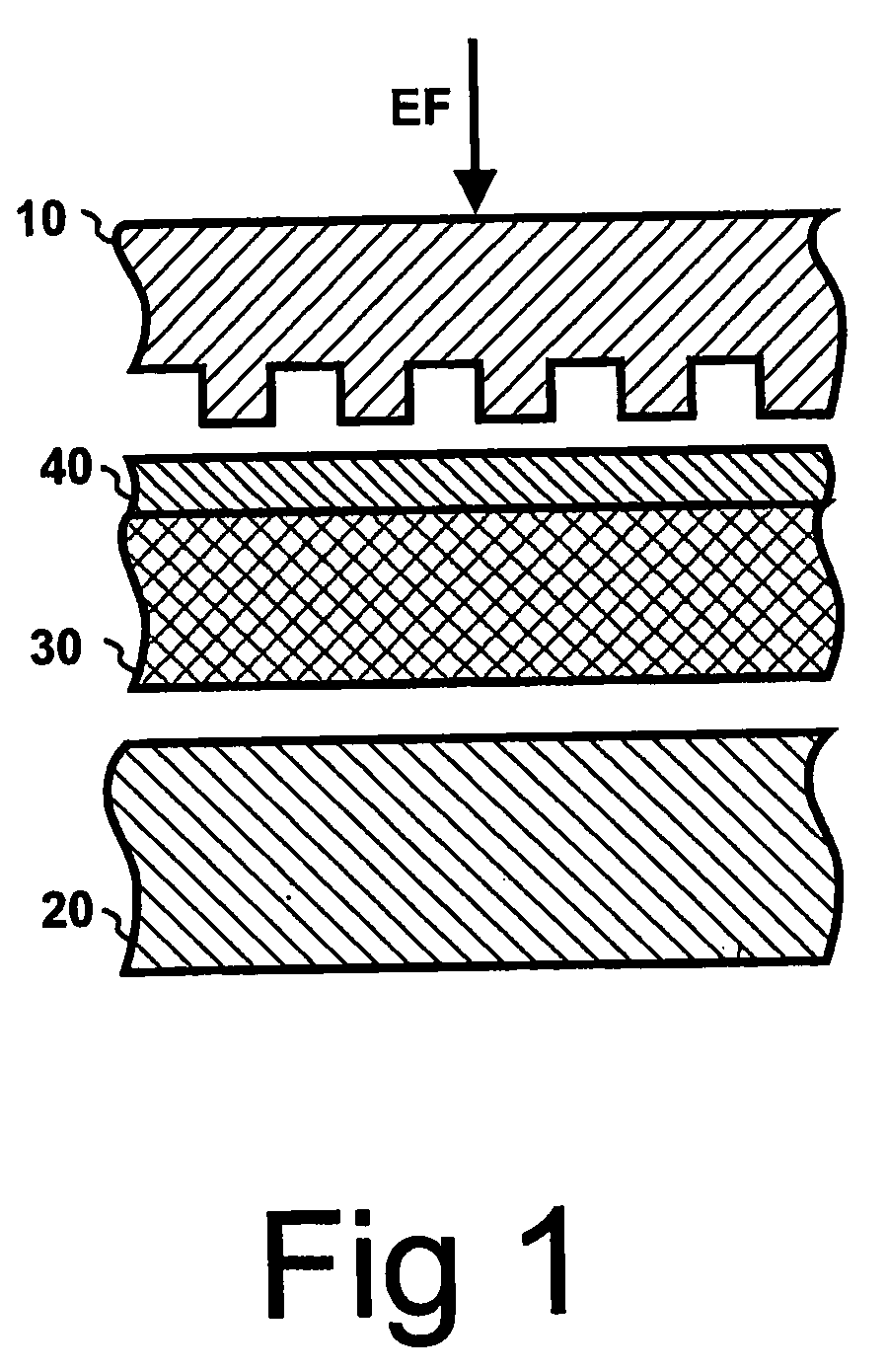
[0027]Referring to FIG. 1, a microstructure is produced on the surface layer 40 of a substrate 30 by pressing the substrate between an embossing roll 10 and a backing roll 20 such that the surface layer 40 of the substrate 30 is shaped to correspond to the relief on the surface of the embossing roll 10. The substrate 30 may be, for example, paper, cardboard or plastic. The surface layer 40 of the substrate 30 may consist of e.g. thermoplastic material, such as polyvinyl chloride, whose viscosity is reduced at high temperature. Examples of suitable surface materials are listed in U.S. Pat. No. 4,913,858. The diffractive microstructure may have e.g. rectangular, symmetrically triangular, asymmetrically triangular or sine-form profile.

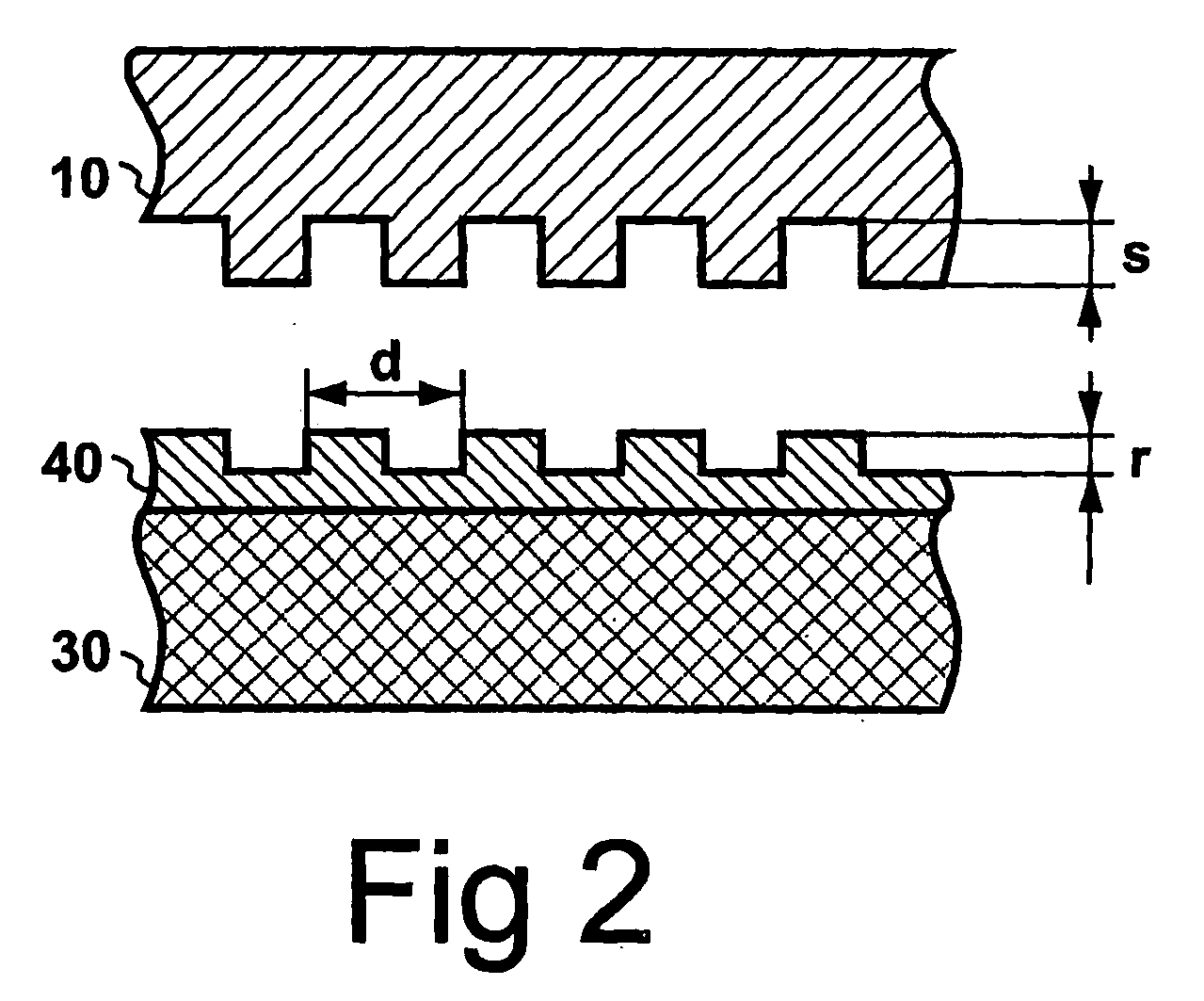
[0028]Referring to FIG. 2, the diffractive microstructure embossed on the surface layer 40 of the substrate 30 corresponds in its shape to the surface structure of the embossing roll 10. The structure is periodical such that a substantially similar shape ...


PUM

PropertyMeasurementUnit
distanceaaaaaaaaaa
distanceaaaaaaaaaa
embossing pressureaaaaaaaaaa

Abstract

A diffractive microstructure is produced on the surface layer of a substrate using an embossing device. The embossing device includes an embossing roll and a backing roll for exerting an embossing pressure on the surface layer of the substrate. The embossing pressure and / or variations in temperature cause deflection of the embossing roll. To compensate for the deflection, the embossing device can set the embossing pressure exerted by the central area of the embossing roll on the surface layer of the substrate to be at least equal to or higher than the embossing pressure exerted by the end areas of the embossing roll on the surface layer of the substrate.

Description

[0001]The present invention relates to a method and device for producing a diffractive microstructure on the surface layer of a substrate by embossing, wherein said device comprises an embossing roll and a backing roll to exert embossing pressure on said surface layer of the substrate.BACKGROUND OF THE INVENTION[0002]Diffractive microstructures may be attached to products for the visual effect given by them, or for authenticating the product.[0003]Diffractive microstructures may be produced for example by embossing the surface layer of a substrate, which has been coated with a suitable lacquer. The coated substrate is pressed between an embossing member and a backing member in the embossing process, wherein the surface of the embossing roll comprises a relief corresponding to the microstructure. The embossing member and the backing member are e.g. rotating rolls. During the embossing process, the backing roll supports the substrate from the back side such that a sufficient pressure,...

Claims


Application Information

Patent Timeline
Patent Type & Authority Applications(United States)
IPC IPC(8): B29D11/00B31F1/07B81CF16CF16C13/00
CPCB31F1/07B31F2201/0753F16C13/024
Inventor KORHONEN, RAIMOKOIVUKUNNAS, PEKKA
Owner AVANTONE OY
Why Eureka
Try Eureka