Dielectric Barrier Discharge Lamp Lighting Device

Inactive Publication Date: 2008-10-16
PANASONIC CORP
View PDF5 Cites 54 Cited by
  • Summary
  • Abstract
  • Description
  • Claims
  • Application Information

AI Technical Summary

Benefits of technology

[0020]In the present invention, the self-resonant frequency of the secondary coil, which is measured with the primary coil of a transformer being open, is set closer to the driving frequency of the driving circuit so that the loss in the transfor

Problems solved by technology

In addition, in the case when the transformer loss becomes very high, since the temperature of the transformer coil becomes higher, an expensive coil having a highly heat-resistant insulating coating needs to be used in order to ensure a sufficient insulating life of the coil, with high costs.
Consequently, this can just suppress the loss in the transformer T but not improve the

Method used


Image

  • Dielectric Barrier Discharge Lamp Lighting Device
  • Dielectric Barrier Discharge Lamp Lighting Device
  • Dielectric Barrier Discharge Lamp Lighting Device

Examples


Example

Embodiment 1

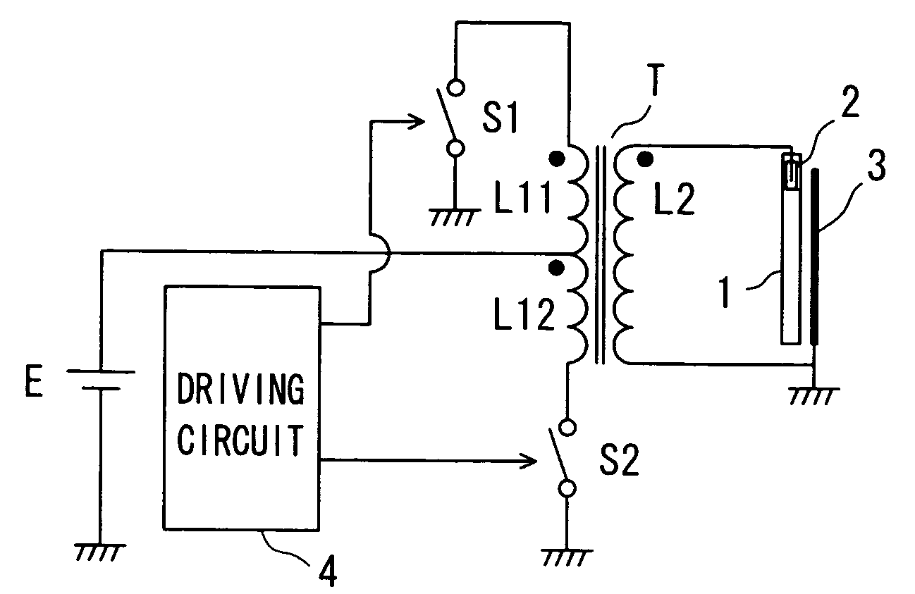
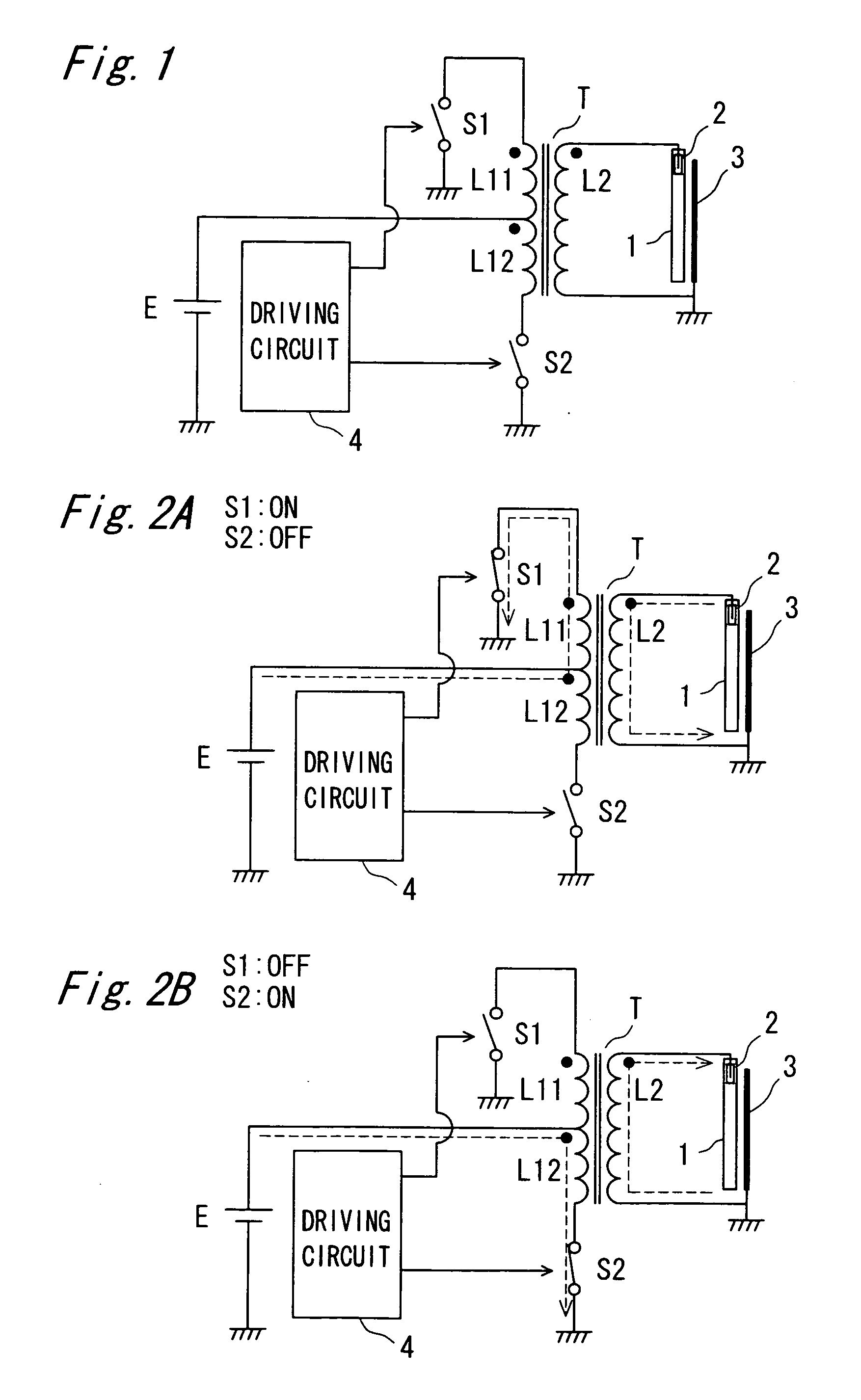
[0046]FIG. 1 is a diagram illustrating a structure of a dielectric barrier discharge lamp lighting device in accordance with embodiment 1 of the present invention.

[0047]In FIG. 1, the lighting device lights a lamp 1, and includes a transformer T that generates a driving voltage to the lamp 1, switching elements S1 and S2 that control an input voltage to be applied to the transformer T, and a driving circuit 4 that drives the switching elements S1 and S2.

[0048]The lamp 1 is a dielectric barrier discharge lamp having an external electrode 2 placed along the axis in the length direction and an internal electrode 3 that is attached to one end of the lamp 1, and is made of a light-transmitting material such as soda glass and borosilicate glass. Here, a mixed gas of 160 Torr composed of Xenon and Argon, is sealed the inside of the lamp 1, and a fluorescent coat film is formed on the inner face of the lamp 1. In the present embodiment, the lamp 1 has a size of φ2.6 mm and 160 m...

Example

Embodiment 2

[0103]FIG. 9 is a drawing that schematically shows a dielectric barrier discharge lamp lighting device in accordance with the second embodiment of the present invention. As shown in FIG. 9, the structure of the second embodiment is different from that of embodiment 1 in that the driving circuit is prepared as a half-bridge inverter. Those components that are the same as those of embodiment 1 are indicated by the same reference numerals, and thus the description thereof is omitted. Moreover, since the operations of the inverter itself have been widely known in general, the detailed description thereof is omitted.

[0104]When using the half-bridge inverter as shown in the present embodiment and outputting the same voltage as that by a push-pull inverter, the coil ratio needs to be doubled in comparison with the push-pull inverter. That is, when the input voltage E is the same, the coil ratio becomes 1:106. Therefore, in comparison with the number of coil turns of the transfo...


PUM


Abstract

A dielectric barrier discharge lamp lighting device includes a transformer that supplies a driving voltage to a dielectric barrier discharge lamp from a secondary coil, and a driving circuit that controls an input voltage to the transformer to supply a driving voltage with a driving frequency fd to the dielectric barrier discharge lamp. The self-resonant frequency fr of the secondary coil, which is measured with the primary coil of the transformer being open, is equal to the driving frequency fd or a frequency in the vicinity of the driving frequency fd. This frequency fr satisfies, for example, 0.9fd≦fr≦1.3fd.

Description

TECHNICAL FIELD[0001]The present invention relates to a dielectric barrier discharge lamp lighting device provided with a driving circuit that includes a transformer.BACKGROUND ART[0002]In recent years, along with the development of liquid crystal techniques, liquid crystal displays have been generally used as information display devices such as televisions and monitors. The liquid crystal display has a structure in which a light source device (backlight) is placed on the back face of the liquid crystal and a light from the backlight transmits through a liquid crystal panel to provide a screen display. With respect to the light source mainly used for the backlight, a light source constituted by a number of capillary cold cathode fluorescent lamps arranged therein has been used in most cases.[0003]Here, researching and developing efforts on a dielectric barrier discharge lamp have been vigorously made so as to apply this to the backlight for liquid crystal. The dielectric barrier dis...

Claims


Application Information

Patent Timeline
IPC IPC(8): H05B37/02H02M7/48H05B41/24
CPCH02M3/3378H05B41/2806Y02B20/22Y02B70/1433Y02B20/00Y02B70/10
Inventor KURACHI, TOSHIAKIKOMINAMI, SATOSHI
Owner PANASONIC CORP
Why Eureka
Try Eureka