Demodulator with Multiple Operating Modes for Amplitude Shift Keyed Signals

Inactive Publication Date: 2008-10-16
MICREL
View PDF9 Cites 43 Cited by
  • Summary
  • Abstract
  • Description
  • Claims
  • Application Information

AI Technical Summary

Benefits of technology

[0005]According to one embodiment of the present invention, a demodulator for demodulating an amplified shift keyed (ASK) signal to provide a digital output signal indicative of the ASK signal includes an envelope detector having an input terminal receiving the ASK signal and an output terminal generating an envelope signal indicative of the data content encoded in the ASK signal; a low-pass filter coupled to receive the envelope signal and generating a filtered envelope signal; a switch coupled

Problems solved by technology

When the demodulator is implemented in an integrated circuit, the capacitor often has to be provided as an external capacitor because it is very costly to incorporate large

Method used


Image

  • Demodulator with Multiple Operating Modes for Amplitude Shift Keyed Signals
  • Demodulator with Multiple Operating Modes for Amplitude Shift Keyed Signals
  • Demodulator with Multiple Operating Modes for Amplitude Shift Keyed Signals

Examples


second embodiment

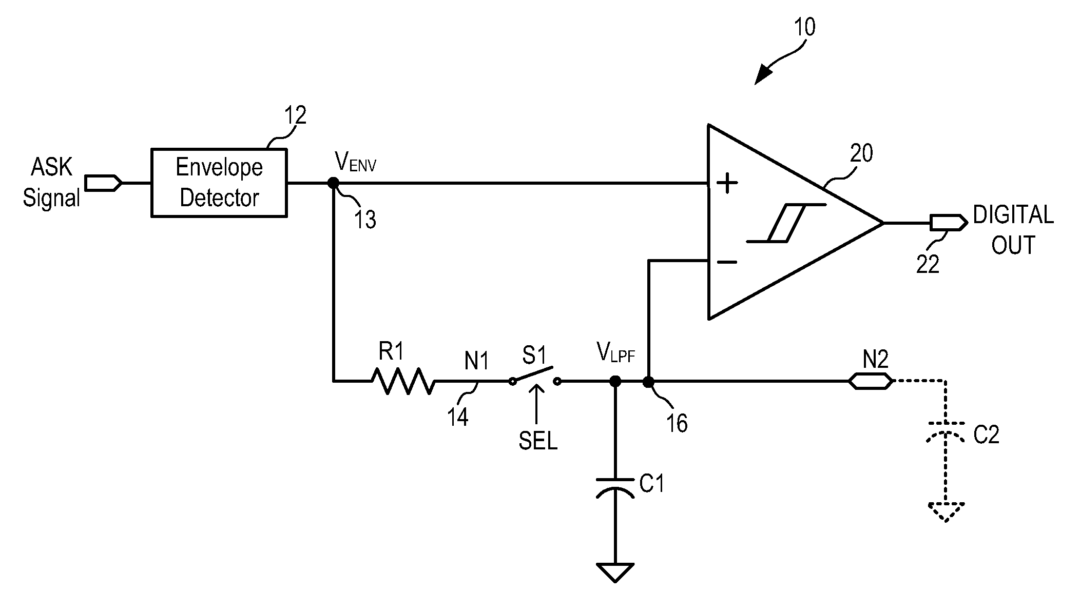
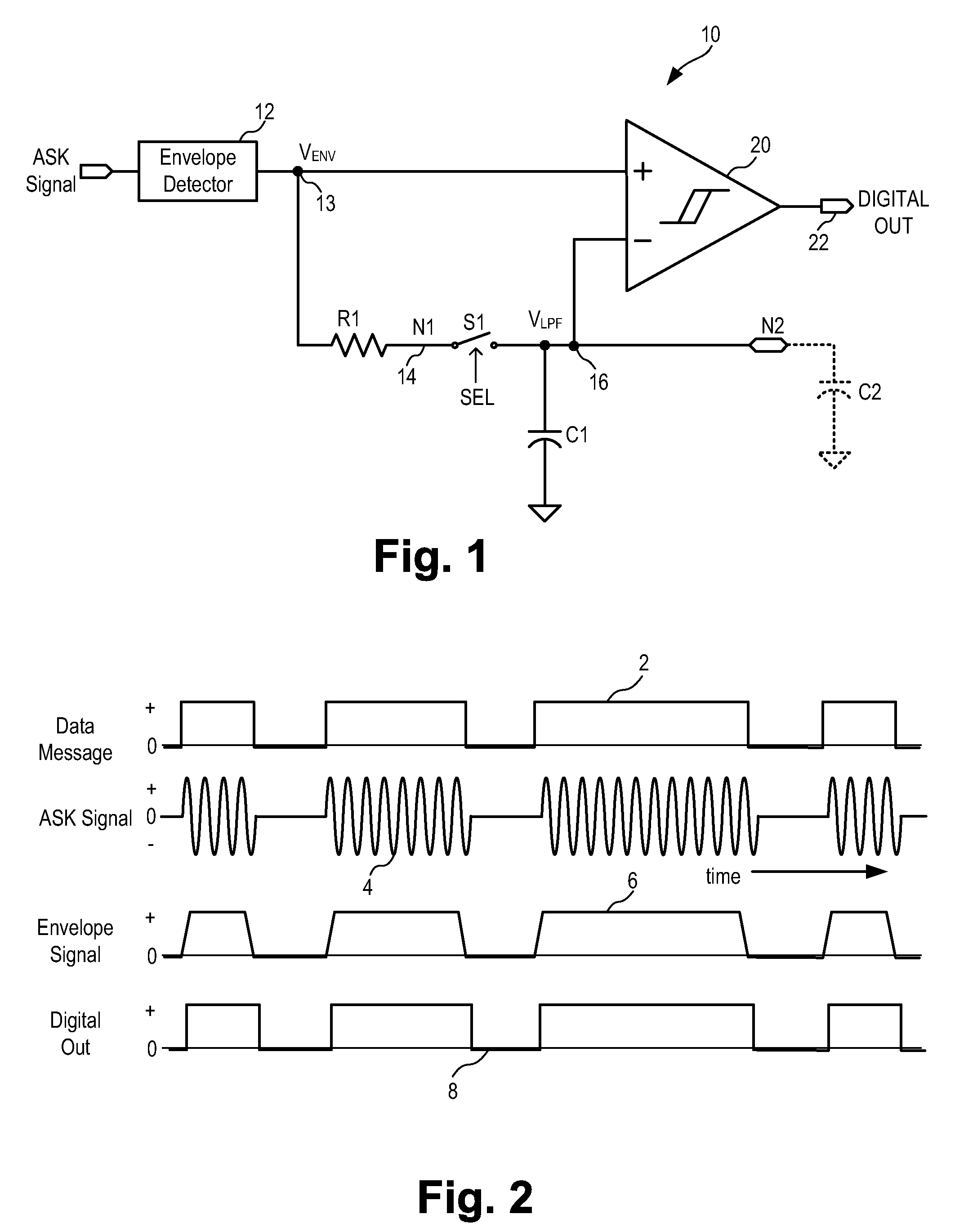
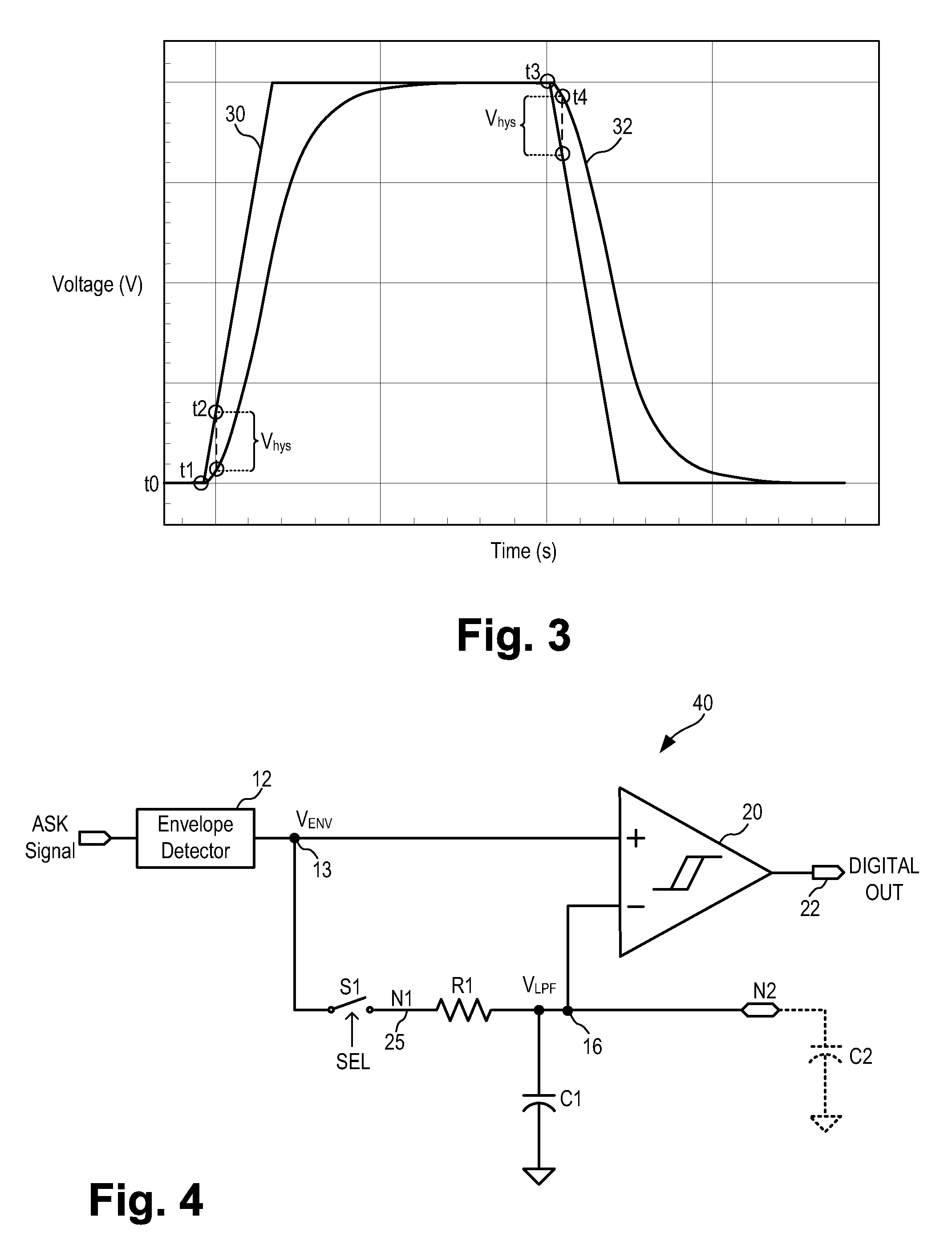
[0040]Furthermore, in the embodiment shown in FIG. 1, the position of resistor R1 and switch S1 can be switched without affecting the functionality of the demodulator. FIG. 4 is a schematic diagram of a demodulator for amplified shift keyed signals according to the present invention. Referring to FIG. 4, switch S1 is connected between node 13 being the output terminal of the envelope detector 12 and a node N1 (or node 25). Resistor R1 is connected between node N1 and a node 16 also denoted as node N2) which is also the inverting input terminal of comparator 20. Capacitor C1 is connected between the inverting input terminal (node 16) of comparator 20 and the ground node. ASK demodulator 40 of FIG. 4 operates in the same manner as the ASK demodulator of FIG. 1. The exact arrangement of resistor R1 and switch S1 in the ASK demodulator of the present invention is not critical to the practice of the present invention.

third embodiment

[0041]In the above-described embodiments, the ASK demodulator of the present invention operates in the analog domain. According to other embodiments of the present invention, the ASK demodulator can operate in the digital domain as well by digitizing the envelope signal. FIG. 5 is a schematic diagram of a demodulator for amplified shift keyed signals according to the present invention. Referring to FIG. 5, an ASK demodulator 50 for demodulating an amplifier shift keyed signal (ASK signal) includes an envelope detector 52, an analog-to-digital converter (ADC) 54, a selection switch S1, a digital low-pass filter 60 and a digital comparator 64. ASK demodulator 50 receives an incoming ASK signal in which the amplitude of a carrier oscillation is switched between two states in accordance with a binary data message. ASK demodulator 50 operates in the same manner as ASK demodulators 10 and 40 to generate a digital output signal indicative of the binary data message encoded in the ASK signa...


PUM


Abstract

A demodulator for demodulating an amplified shift keyed (ASK) signal includes an envelope detector generating an envelope signal, a low-pass filter generating a filtered envelope signal, a switch coupled to disengage the low-pass filter in response to a first control signal, a comparator with hysteresis comparing the envelope signal and the filtered envelope signal. In operation, the switch is open or close in response to the first control signal to cause the demodulator to operate in one of multiple operation modes. In one operation mode, the demodulator uses a small capacitor to form a low-pass filter having a cut-off frequency equal to or greater than the bit-rate of the ASK signal and the demodulator receives an ASK signal having any coding pattern, including ASK signals having unequal number of 1's and 0's.

Description

FIELD OF THE INVENTION[0001]The invention relates to demodulators for demodulating radio frequency signals and, in particular, to a demodulator for demodulating amplitude shift keyed (ASK) data signals.DESCRIPTION OF THE RELATED ART[0002]Amplitude shift keying (ASK) is a form of modulation which represents digital data as variations in the amplitude of a carrier wave. The simplest and most common form of ASK is referred to as on-off keying (OOK) where the ASK modulation operates as a switch, using the presence of a carrier wave to indicate a binary one and its absence to indicate a binary zero. In other words, the data bits of an ASK signal are each characterized by either an absence of pulses or a burst of pulses at a predetermined frequency. Amplitude-shift keying requires a high signal-to-noise ratio for their recovery, as by their nature much of the signal is transmitted at reduced power. The advantage of ASK radio systems is the simplicity of the transceiver topology and low cu...

Claims


Application Information

Patent Timeline
IPC IPC(8): H03K9/02
CPCH04L27/06
Inventor PETTERSEN, FRED-JOHANSTOKKE, BJORN
Owner MICREL
Why Eureka
Try Eureka