Dental abutment blank with preformed passage

a technology of abutment and passage, which is applied in the field of dental abutment blanks, can solve the problems of easy damage to the dental blank, difficulty in affixing the connector, and difficulty for operators, and achieve the effect of facilitating the fixation of the dental screw and facilitating the dental connection

Inactive Publication Date: 2008-10-16
VIDENT
View PDF14 Cites 25 Cited by
  • Summary
  • Abstract
  • Description
  • Claims
  • Application Information

AI Technical Summary

Benefits of technology

[0004]The present invention is directed to a dental abutment blank having a preformed passage that is adapted for use as a reference location by a milling machine and / or a formation to facilitate a dental connection to the blank prior to milling. The blank has at least one passage extending between two opposing ends of the blank. As a reference location, the passage is generally concentric or axially aligned with the blank. As a formation facilitating a dental screw fixation, the passage defines a dental connection axis in the blank.
[0005]In one embodiment, the blank has at least one passage that extends between two opposing ends. The passage includes a larger portion and a smaller portion which are configured to receive a connector such as dental screw fixation including a screw and a nut, for an internal mount or an external fixation on the blank. The blank may be mounted on a mandrel with the passage generally parallel (and coaxial) with the mandrel, or with the passage generally perpendicular to the mandrel. In any case, the blank provides an opening of the passage or an end of the affixed dental screw fixation that can be read, detected or sensed by a CAD / CAM machine for use as a reference location.
[0006]In a more detailed embodiment, the blank may have a cylindrical form or a rectangular solid form with one smaller end and one larger end with a tapered section adjacent the smaller end to better resemble the bottom or gumline of a crown. And depending on the type of dental screw fixation desired, the passage may have a longer narrower portion and a shorter wider portion, or a shorter wider portion and a longer narrower portion.
[0007]Accordingly, the present invention includes a dental blank having a generally solid form with two opposing ends, the block having a preformed passage extending between the two ends. The block may have a cylindrical form or a rectangular form. One of the ends may be smaller with an adjacent tapered section so that the blank better resembles a crown-like shape. The passage is configured to receive a dental screw fixation, which may include a screw and a nut. The dental screw fixation may be mounted to the blank in an external or an internal configuration. Either end of the block carrying the dental screw fixation is adapted for mounting to a mandrel prior to milling of the blank, to expose either the dental screw fixation or an opening of the passage distal to the mandrel. Once in a CAD / CAM milling machine, either the exposed dental screw fixation or the exposed opening of the passage is sensed as a reference location for locating the blank prior to milling.
[0008]A method to provide a dental blank adapted for use as a reference location by a milling machine and / or a formation to facilitate a dental screw fixation to the blank prior to milling, includes forming a blank and providing a passage through the blank, for example, by drilling. The method also includes providing such a passage prior to milling the blank and / or mounting the blank on a mandrel. The method further includes mounting a dental screw fixation in the passage to provide an internal or external connection for a dental implant, dental implant abutment or orthodontic implant prior to milling the blank and / or mounting the blank on a mandrel. The method further includes using the passage in the blank or a distal portion of the mounted dental screw fixation (e.g., a screw head and / or nut) as a reference location for milling the blank.

Problems solved by technology

However, difficulties have been encountered when affixing the connector to the artificial crown, particularly where the connector requires a deep hole to be drilled in the artificial crown.
Moreover, CAD / CAM milling machines, though well suited for milling a dental blank to great precision and accuracy, can pose a challenge for operators when the milling process is initiated.
That is, the first contact between the drill bit and the dental blank if not executed properly can readily damage the dental blank.

Method used


Image

  • Dental abutment blank with preformed passage
  • Dental abutment blank with preformed passage
  • Dental abutment blank with preformed passage

Examples


Embodiment Construction

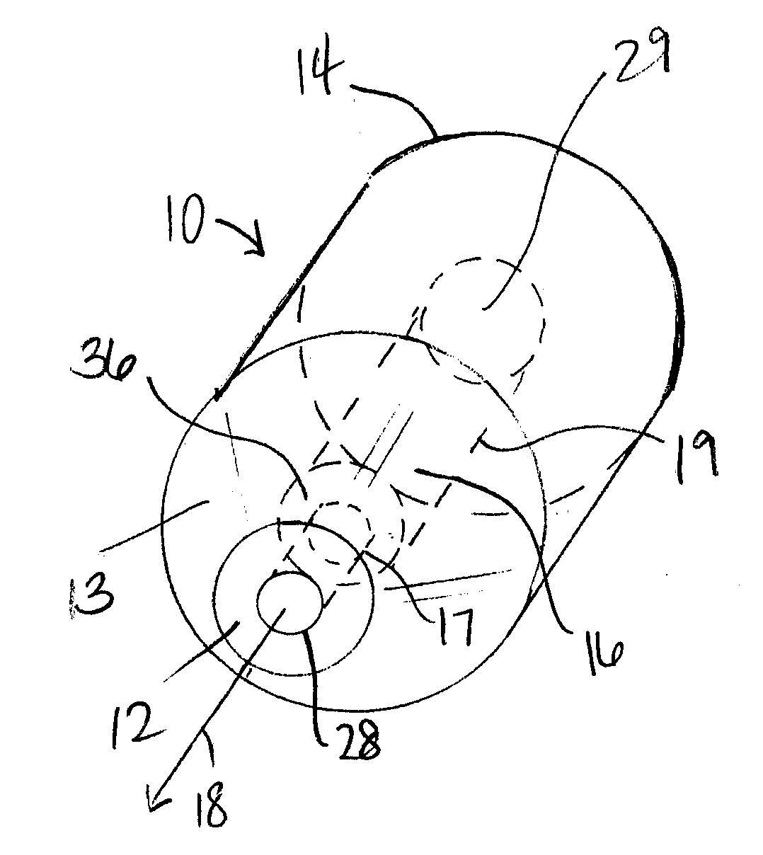
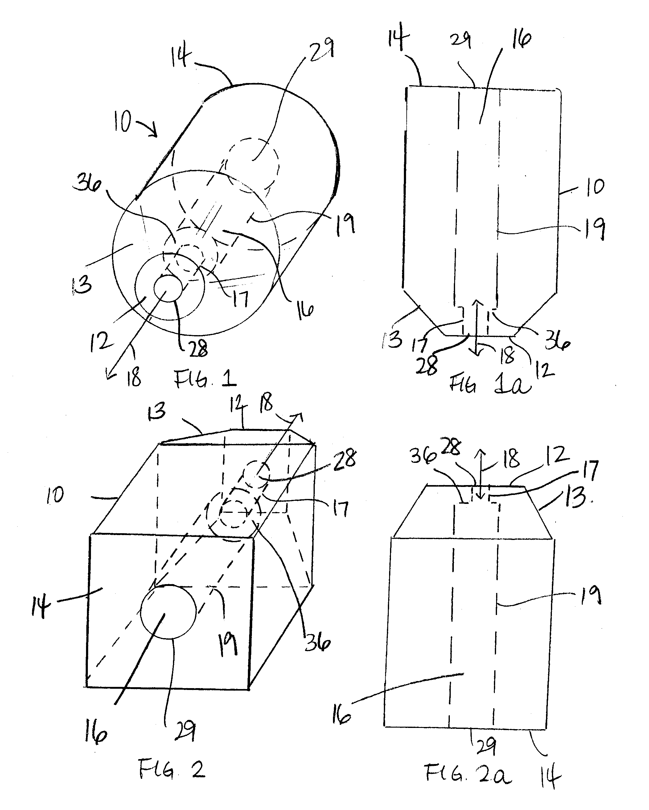
[0029]FIGS. 1, 1A, 2 and 2A illustrate embodiments of a dental blank in accordance with the present invention. The blank 10 is a solid form constructed of a machinable material suitable for dental applications, including ceramic, plastic, composite, hybrid of ceramic and resin and / or combination thereof. The blank 10 may have a generally circular-cross section such that the blank takes on a cylindrical form (FIGS. 1 and 1A), or the blank may have a generally rectangular or square cross section such that the blank takes on a rectangular block form (FIGS. 2 and 2A). In the illustrated embodiment of FIGS. 1 and 1A, the blank has two opposing ends 12 and 14. Adjacent the end 12 is a tapered section 13 with a decreasing diameter or cross section, whereas opposing end 14 has the same diameter or cross section as the bulk or main portion of the blank. As understood by one of ordinary skill in the art, the blank can assume a variety of different configuration as desired or appropriate, incl...


PUM


Abstract

A dental blank has having a preformed passage configured to receive a dental screw fixation before or after milling by a CAD/CAM milling machine which can detect an exposed dental screw fixation or an exposed opening of the passage as a reference location. A method to provide a dental blank adapted for use as a reference location by a milling machine and/or a formation to facilitate a dental screw fixation to the blank, includes forming a blank and providing a passage through the blank, for example, by drilling.

Description

CROSS-REFERENCE TO RELATED APPLICATIONS[0001]This application claims the benefit of U.S. Provisional Patent Application No. 60 / 911,050, filed Apr. 10, 2007, which is hereby incorporated by reference as if fully stated herein.FIELD OF INVENTION[0002]The present invention relates to a dental abutment blank adapted for use with a dental implant, and a method of making the same.BACKGROUND OF INVENTION[0003]Dental implants have been in use to replace natural teeth. Dental implants not only allow people to chew with comfort, but are an effective means to avoid loss of the bone in the jaw when dentition is lost. Different types of dental implants are known. In many cases, the dental implant includes a 3.5-5.5 mm metallic bone screw that serves as a tooth root, which is inserted surgically into the jawbone or upper maxillary. A cap, a bridge or denture (supporting an artificial crown(s)) can then be anchored to the implant by means of an abutment on which artificial teeth are placed. To mak...

Claims


Application Information

Patent Timeline
Patent Type & Authority Applications(United States)
IPC IPC(8): A61C13/225
CPCA61C13/0022
Inventor MCGUIRE, JAMES A.BAKER, WILLIAMTAYLOR, JASON R.
Owner VIDENT
Why Eureka
Try Eureka