Bone-compliant femoral stem

a femoral stem and bone technology, applied in the field of implantable bone prostheses, can solve the problems of buckling and other non-uniform deformation mechanisms, higher stem stress, and correspondingly decreased stem load carrying capacity,

Active Publication Date: 2008-10-16
SIDEBOTHAM CHRISTOPHER G
View PDF22 Cites 57 Cited by
  • Summary
  • Abstract
  • Description
  • Claims
  • Application Information

AI Technical Summary

Benefits of technology

[0020]The present invention provides a canine femoral stem that is compliant with the stiffness and elastic modulus of bone tissue, so that load is transferred between the bone and the implant without creation of bone separation or crack formation. The compliant elastic stiffness or modulus of the canine femoral stem provides load transfer without crack formation from the initial time period immediately after implant surgery to complete healing of implanted tissue by bone ingrowth. Due to the intimate contact between the prepared bone and the bone compliant canine femoral stem during the healing period, a long term permanent bond between the implant and the underlying bone structure is made possible, so that extended motion meeting the needs of a dog is provided. Once implanted, the device functions without corrosion or rejection reactions throughout the lifetime of the dog.
[0024]Our present invention provides a bone-compliant canine femoral stem, which is characterized by having modulus at the bone-contacting surface matching that of the natural bone, enabling load transfer without formation of cracks at the interface. The low modulus in the bone contact region of the upper portion of the canine femoral stem is formed by a thick titanium porous body diffusion bonded or mechanically attached to a central solid metallic core body. This low modulus is due to inclusion of multiple levels of porosity, which results in large movement at low loads or an effective elastic modulus, which is small. At the region of the porous body which contacts the titanium central core, the modulus is lesser than that of titanium, but is much larger than that of the porous body at the bone contacting region. The modulus falls rapidly in a progressively decreasing fashion along the thickness of the porous titanium body as a function of distance from the titanium central core.
[0026]When the bone compliant canine femoral stem is inserted into a surgically prepared bone cavity, the lower portion of the bone compliant femoral stem is firmly fitted into the cavity providing initial stability immediately after surgery. The bone ingrowth occurs both in the lower and upper portion of the bone-complaint canine femoral stem since the overall elastic modulus of the diffusion bonded or mechanically attached porous body and the compression or injection molded lower portion is very similar to the bone tissue. The load is therefore transferred from the central solid metallic core to the bone tissue without creating delamination or crack formation at the bone contacting regions of the bone-compliant canine femoral stem.

Problems solved by technology

It also exhibits higher stem stresses upon loading of the implant.
However, this milling or material removal operation correspondingly decreases the load carrying capacity of the stem and its flexure behavior is subject to buckling and other non-uniform deformation mechanisms.
At the contact location between bone and the implant, the modulus or stiffness has a very large change preventing proper load transfer to the bone.
This, in turn, leads to crack formation at the bone-implant interface.
However, as the biodegradable anchor deteriorates and bone regrowth occurs, the anchor and its attachment is weakened.
During this interim healing period, the implant is clearly unstable and is subject to movement causing bone-healing problems.
Therefore, it is not clear how the metal provides any load bearing support.
The decreased wall thickness of the stem at the distal end may result in buckling or collapse of the stem during torsional or bending deformation.
The presence of slit complicates the deformation behavior since the slit can open out under load.
Therefore, its contact with bone tissue will result in shear separation at the interface.
There is no means provided to provide a bone-compliant joint since all the materials used for the artificial hip joint are very high modulus metallic materials.
The assembly of particles provide no elastic modulus representing load carrying capability, since they fall apart easily.
This method creates a dangerous situation when the implant is first incorporated since the metallic core is not in any manner attached to the anchor.
Moreover, the ingrowth of the bone into the anchor progressively destroys the integrity of the resorbable layer, and the bone structure is yet to be built completely for load sharing.
The presence of a non-load carrying metallic core reduces the overall cross section of the bone reducing its load capacity.
Since the foam is projected to be the weakest element, the orthopedic implant is not securely attached to the bone structure even when bone ingrowth occurs within the bone.
Therefore, the orthopedic implant will experience movement under load, creating a dangerous situation.
The grooves reduce the stiffness of the femur implant.
In addition, the presence of grooves decreases the load carrying capacity of the femoral implant.
This significant mismatch in elastic modulus at the distal section takes away any benefit of reduced elastic modulus at the porous proximal section.
However, the bond between the polymeric proximal body and the metallic core may be inadequate to produce a successful orthopedic implant.
When stiffness mismatch is present, the same load carried elongates the implant member differently than the bone tissue resulting in crack formation or implant separation.

Method used


Image

  • Bone-compliant femoral stem
  • Bone-compliant femoral stem
  • Bone-compliant femoral stem

Examples


Embodiment Construction

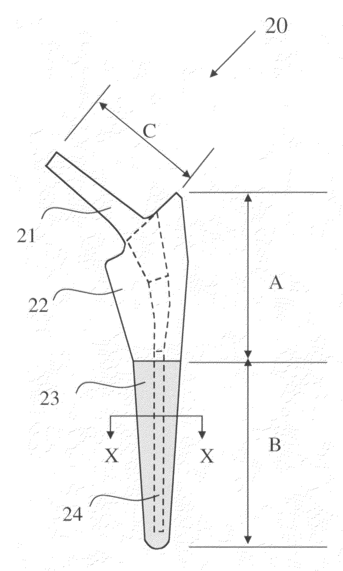
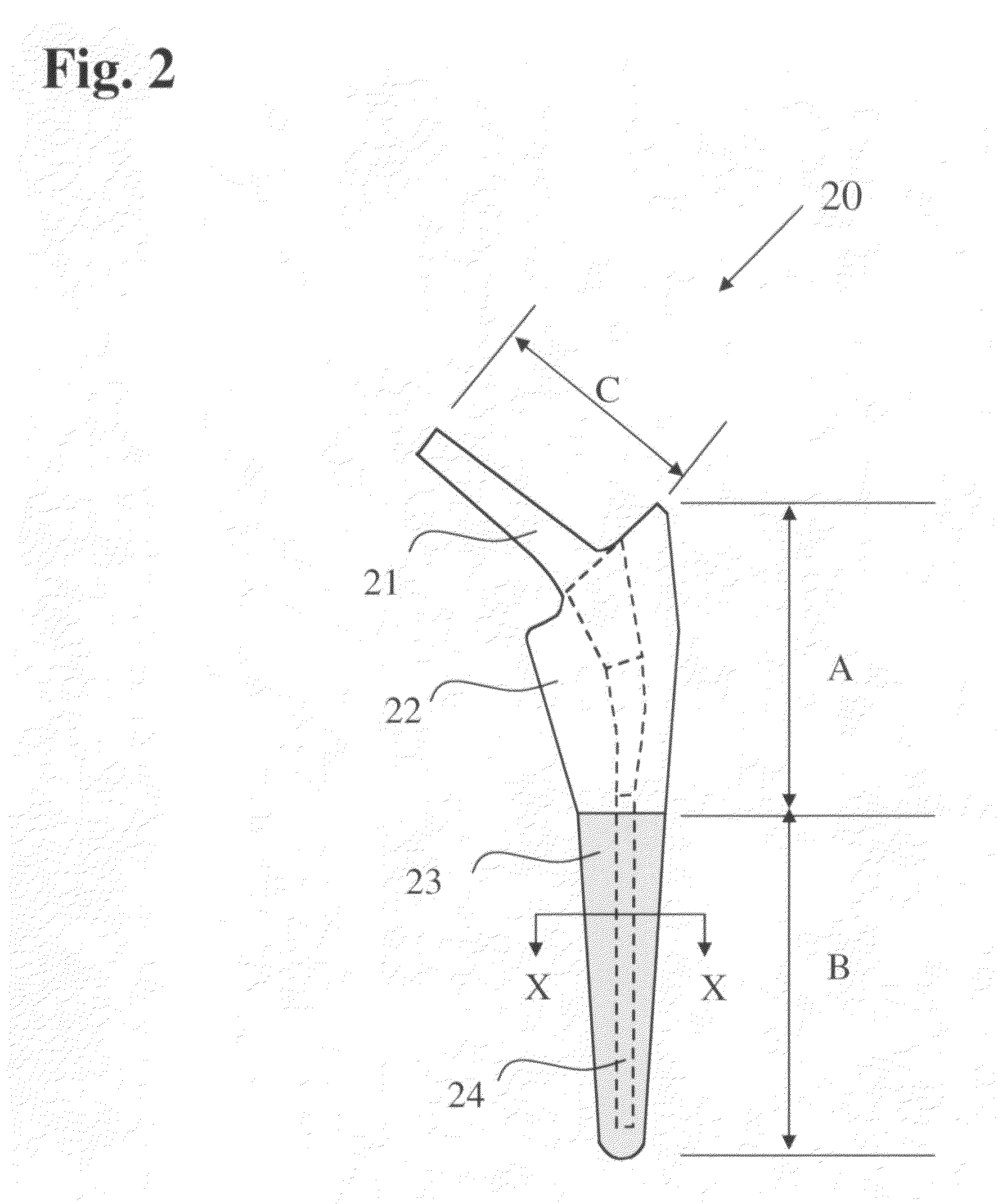
[0035]This invention relates to a bone-compliant femoral stem which may be attached using cement or by way of a cementless procedure. The bone-compliant femoral stem is herein described with particular reference to use in canines. However, it will be understood that the principles of the invention are fully applicable to use of the femoral stem in humans. The bone-compliant canine femoral stem comprises a slender biocompatible metallic support member made from a Ti alloy, preferably Ti—Al—V alloy or a chromium alloy. The dimensions of the slender metallic body are generally much less than the surgically prepared bone cavity and are of a size sufficient to withstand the stresses provided by a canine patient immediately after a surgical procedure. The slender metallic support member is completely surrounded in the proximal and distal region by a porous biocompatible member, preferably a titanium member, which is diffusion bonded or mechanically attached to the slender metallic support...


PUM

PropertyMeasurementUnit
thicknessaaaaaaaaaa
thicknessaaaaaaaaaa
thicknessaaaaaaaaaa

Abstract

A femoral stem for canines or humans is made bone-compliant by use of a thick sintered titanium body in a proximal bone contacting region and a polymeric or ceramic body in a distal bone contacting region of the femoral stem. An elastic modulus is thereby engineered to match that of bone tissue. The porous sintered titanium body is created by sintering spheres of titanium. It is bonded to a central solid biocompatible metallic body by diffusion bonding. The distal region has a biocompatible polymeric body or biocompatible cement body. When compression molded the distal region develops an elastic modulus matching that of bone tissue. The proximal region has a porosity designed to encourage bone ingrowth.

Description

BACKGROUND OF THE INVENTION[0001]1. Field of the Invention[0002]The present invention relates to implantable bone prostheses; and, more particularly, to a bone-compliant femoral stem for canines or humans having compatibility with natural bone.[0003]2. Description of the Prior Art[0004]Many patents address issues related to canine femoral and / or human femoral stems. Some patents address adding geometrical features or cracks within the femoral stem to reduce the stiffness of the femoral stem and bring it closer to the stiffness of bone tissue.[0005]U.S. Pat. No. 4,808,186 to Smith discloses a controlled stiffness femoral hip implant for use in the hip or other appropriate body joint. In a hip, a ball member fixed to the femur is rotatably engaged with a cup-shaped socket member fixed to the acetabulum of the pelvic bone. The ball member is mounted on one end of a femoral component, which has an elongated stem receivable in the intramedullary canal of the femur. The stem has a longitu...

Claims


Application Information

Patent Timeline
Patent Type & Authority Applications(United States)
IPC IPC(8): A61F2/36
CPCA61F2250/0018A61F2250/0024A61F2250/0026A61F2310/00023A61F2310/00029A61F2310/00407A61F2310/00413A61F2310/00491A61F2310/00544A61L27/06A61L27/30A61L27/34B22F7/004B22F2003/242B22F2003/248B22F2998/10B22F2999/00C08L71/12B22F3/1112B22F3/1146B22F3/24B22F3/1266A61F2/30767A61F2/30907A61F2/3094A61F2/36A61F2/3662A61F2/367A61F2/3676A61F2002/30013A61F2002/30014A61F2002/30064A61F2002/30138A61F2002/30322A61F2002/30703A61F2002/30919A61F2002/30929A61F2002/30957A61F2002/30967A61F2002/30968A61F2002/30971A61F2002/30973A61F2002/3625A61F2002/4631A61F2230/0017A61F2002/30011A61F2002/307
Inventor SIDEBOTHAM, CHRISTOPHER G.
Owner SIDEBOTHAM CHRISTOPHER G
Why Eureka
Try Eureka