Railroad signal line attachment clip

a technology for rails and rails, applied in the direction of tracks, superstructures, constructions, etc., can solve the problems of affecting the safety of rails, so as to improve the electrical contact and improve the electrical conductivity

Inactive Publication Date: 2008-10-23
CCI THERMAL TECH INC
View PDF23 Cites 21 Cited by
  • Summary
  • Abstract
  • Description
  • Claims
  • Application Information

AI Technical Summary

Benefits of technology

[0008]Another objective of the present invention is to provide an anchor for holding components relative to the rail without that may be quickly and securely attached to the rail.
[0010]Accordingly systems and methods (i.e, utilities) for directly contacting a signal conductor to a surface of a track rail is provided that further incorporates the use of a mechanical anchor or clamp to maintain a signal conductor (or other electrical conductor) in a fixed positional relationship with a railroad track component. The utilities may include preparing a contact area of a railroad track component, attaching a mechanical anchor to the railroad track component and compressing an electrically conductive portion of a signal conductor between a portion of the anchor and the track rail. An adhesive may be applied to the contact area an / or the signal conductor. For instance, such an adhesive may be applied to cover exposed surfaces of the signal conductor and / or a prepared surface of the track rail. Such an adhesive may prevent corrosion at or around the contact area.
[0011]According to a first aspect, an anchor is provided for use in connecting a component to a track rail. The anchor includes a first body member having a first rail contact surface for engaging a first rail surface. The anchor also includes a second body member having a second rail contact surface for engaging a second rail surface. The first and second body members are moveably connected. In this regard, the first and second body members may be moved relative to one another to compress a portion of a rail therebetween. A pawl is attached to one of the body members and is adapted to engage the engagement surface of the body member. Such a pawl may permit movement between the body members in substantially a single direction. That is, while some movement may be permitted between the body members, the pawl will generally prevent unintended withdrawal of one of the body members relative to the other body member such that a compressive force may be maintained between opposing surfaces of the track rail.
[0015]According to another aspect, a method is provided for engaging a signal wire with the track rail. The method includes placing a portion of a track rail between first and second contact surfaces of a rail anchor. A signal wire may then be placed between the surface of the track rail and one of the contact surfaces of the anchor. At this time, a first portion of the rail anchor may be advanced towards the second portion of the rail anchor such that the first and second contact surfaces are compressed together. In this regard, the signal wire may be compressed against a surface of the track rail. In conjunction with such advancement, a pawl associated with one portion of the rail anchor engages an engagement surface of the other portion of the rail anchor to prevent withdrawal of these portion relative to one another. In this regard, upon being advanced relative to one another, the first and second portions may maintain a compressive force therebetween.
[0018]The method may further include cleaning a surface of the track rail, for instance, the surface to which the signal wire and / or a contact surface of the anchor may be applied. Such cleaning / preparation may allow for improving electrical contact between the track rail and the signal line. For instance, such preparation may entail the removal of, for example, rust and / or other surface imperfections / oxidations. Such preparation may be performed by chemically treating or abrading the surface of the track rail. Further, the prepared area may then be cleansed (for example, utilizing alcohol, etc.) to remove any remaining particulates. In a further arrangement, an adhesive may be applied over a portion of a contact area between the signal wire and the track rail. Such adhesive application may include encapsulating all or a portion of one of the contact surfaces of the anchor. In a further arrangement, electrically conductive tapes may be applied to the surface of the track rail and / or the electrically conductive portion of a signal line. Such electrically conductive tapes may provide improved electrical conductivity therebetween.

Problems solved by technology

Such techniques are typically labor intensive.
Further if drilling or welding is not correctly perfumed, the structural integrity of a rail may be damaged.

Method used


Image

  • Railroad signal line attachment clip
  • Railroad signal line attachment clip
  • Railroad signal line attachment clip

Examples


Embodiment Construction

[0028]The present invention is directed to the use of an adjustable rail clamp to connect a signal conductor to a railroad track rail. It will be appreciated that the invention is applicable to the electrical interconnection of any electrical conductor to a track rail for any purpose.

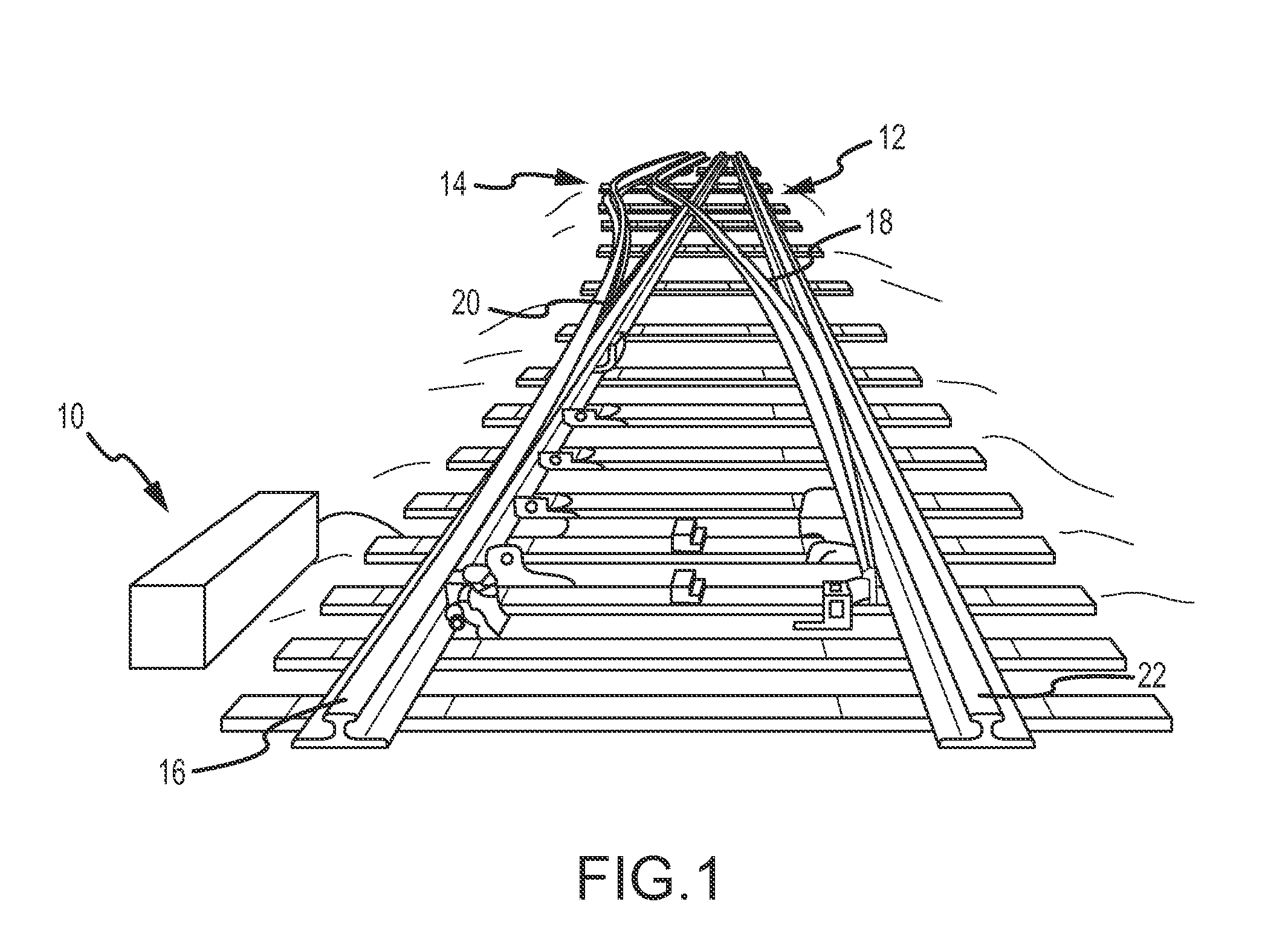
[0029]Referring to FIG. 1, a section of railroad track is generally identified by the reference numeral 10. As shown, the section of railroad track 10 includes a switching mechanism to switch trains between first and second tracks 12, 14. Each set of tracks 12, 14 includes two of track rails. As shown, the first track 12 includes a switching rail 12a and a stationary or stock rail 12b (also known as a running rail). Likewise, the second track 14 includes a stock rail 14a and a switching rail 14b. For purposes of controlling traffic, each track rail 12, 14 is electrically interconnected to a signal providing and monitoring system 8 that is located in proximity to the rail connection location.

[0030]The si...


PUM


Abstract

The present disclosure relates to a system and method for non-invasively attaching components to railroad track rails. More specifically, an anchor is provided that securely fastens to the track rail in a non-invasive manner for holding one or more signal lines to a surface of the track rail. In one embodiment, the non-invasive anchor utilizes a compressive force to clamp to a flange portion of the track rail. In this regard, first and second body members of the anchor may be advanced toward the toward opposing surfaces of track rail to compress the component between a portion of the anchor and a surface of the track rail. In one embodiment, a pawl prevents the withdrawal of these body members from one another such that the compressive force may be maintained once the anchor is applied to the track rail.

Description

CROSS-REFERENCE[0001]This application claims the benefit of U.S. Provisional Application No. 60 / 912,595 having a filing date of Apr. 18, 2007, the entire contents of which are incorporated herein by reference.FIELD OF THE INVENTION[0002]The present invention relates to a non-invasive system and method for forming an electrical connection between a railroad track rail and any electrical conductor, for example signal lines, wires or cables.BACKGROUND OF THE INVENTION[0003]In typical railroad systems, a length of many miles of track may be divided into a plurality of successive adjacent blocks that may be further subdivided into cut circuits (collectively track sections) for control, monitoring, heating and / or maintenance purposes. Each track section forms a track circuit wherein the track rails are utilized to carry electrical signals. In some cases, the track rails in each track section are electrically insulated from the track rails of adjacent track sections such that each circuit ...

Claims


Application Information

Patent Timeline
Patent Type & Authority Applications(United States)
IPC IPC(8): E01B26/00
CPCE01B26/005E01B26/00
Inventor REICHLE, DAVID L.
Owner CCI THERMAL TECH INC
Why Eureka
Try Eureka