Antenna, and wireless module, wireless unit and wireless apparatus having the antenna

a technology of wireless module and antenna, which is applied in the direction of antenna, antenna details, elongated active element feed, etc., can solve the problems of poor usability of monopole antenna having about 20 cm in length as in the conventional mobile television receiver, and achieve the reduction of transmission line length, capacitive component and inductive component of transmission lines, and high reception sensitivity.

Inactive Publication Date: 2008-10-23
MAXELL HLDG LTD
View PDF9 Cites 9 Cited by
  • Summary
  • Abstract
  • Description
  • Claims
  • Application Information

AI Technical Summary

Benefits of technology

[0023]In the wireless module mentioned above, the frequency band of any radio signal that the antenna transmits / receives is narrower than the entire frequency band used for a wireless system to transmit / receive radio signals through the antenna, and the central processing unit causes the resonant frequency of the antenna to change when any radio signal is transmitted or received, thus enabling the wireless system to transmit / receive radio waves over the entire frequency band for use.
[0029]In the wireless apparatus mentioned above, the frequency band of any radio signal that the antenna transmits / receives is narrower than the entire frequency band used for the wireless system to transmit / receive the radio signals through the antenna, and the central processing unit changes the resonant frequency of the antenna when any radio signal is transmitted / received, thus enabling the wireless system to transmit / receive the radio signals over the entire frequency band for use.
[0030]According to the invention, since the antenna is formed of a transmission line, the Q indicative of the sharpness of the resonance is high. In addition, the antenna has a resonant frequency determined by the capacitive component of the variable capacitance means and the inductance component of the inductive transmission line. Thus, the resonant frequency has a narrow frequency band. In addition, if the capacitive component of the variable capacitance means is changed to control the resonant frequency, the antenna can have high receiving sensitivity to each of narrow frequency bands and also over a wide frequency band.
[0031]In addition, when a particular resonant frequency is obtained, the capacitive component and inductive component of the transmission lines can be reduced by the capacitive component of the variable capacitance means as compared with the case where there is no variable capacitance means. Thus, since the capacitive component and inductive component of the transmission lines are proportional to the tangent of their lengths, the transmission line lengths can be reduced, and thus a small-sized antenna can be produced.

Problems solved by technology

However, the monopole antenna having about 20 cm in length as in the conventional mobile television receiver is still poor in its usability.

Method used


Image

  • Antenna, and wireless module, wireless unit and wireless apparatus having the antenna
  • Antenna, and wireless module, wireless unit and wireless apparatus having the antenna
  • Antenna, and wireless module, wireless unit and wireless apparatus having the antenna

Examples


first embodiment

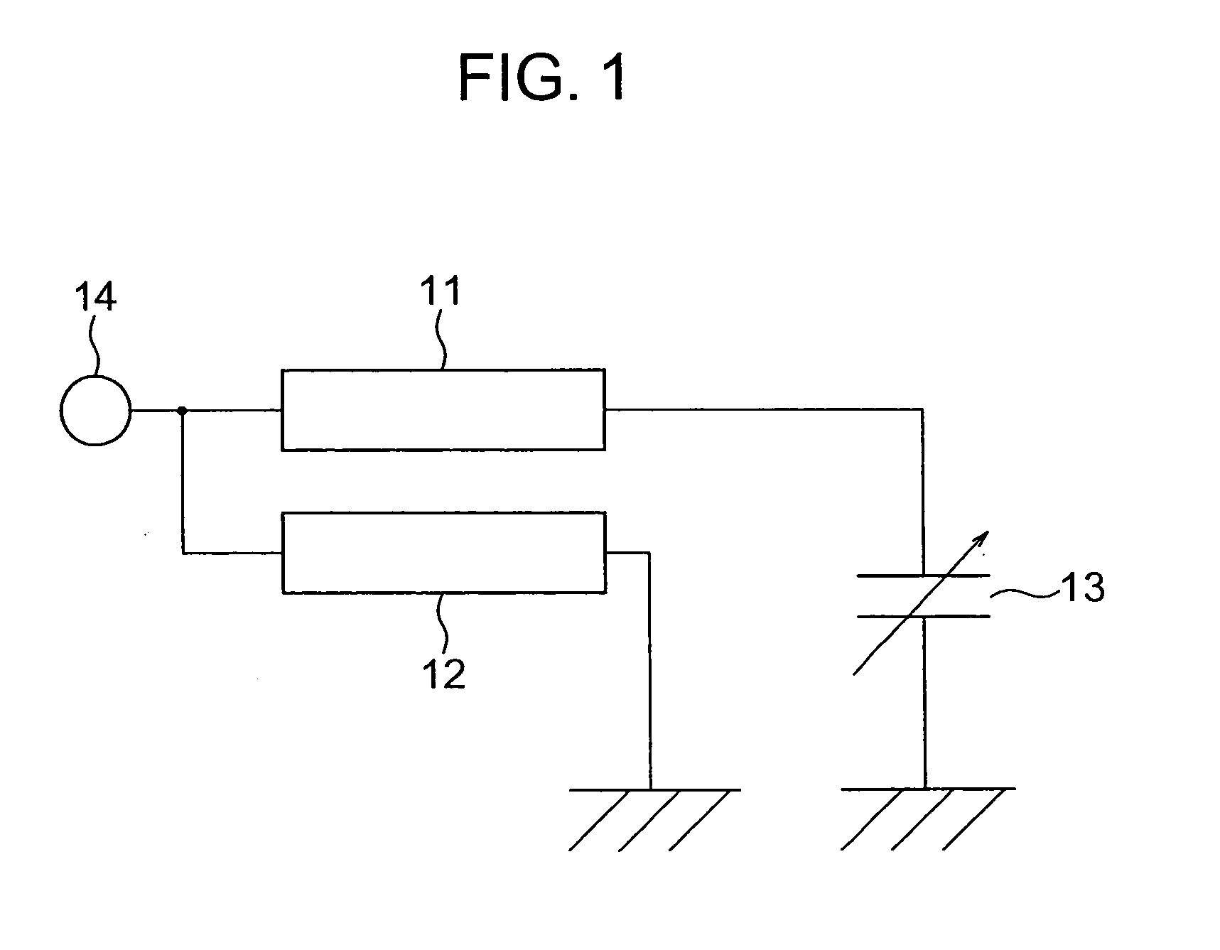
[0052]FIG. 1 is a diagram showing an example of the fundamental structure of an antenna according to the invention. Referring to FIG. 1, the transmission line is formed of two transmission lines 11 and 12. The antenna is comprised of the two transmission lines 11, 12 of λ / 4 or less electric wavelength, variable capacitance means 13 and feed point 14.

[0053]One end of the variable capacitance means 13 is electrically grounded, and the other end is connected to one end of the transmission line 11. The other end of the transmission line 11 is connected to the feed point 14 and to one end of the transmission line 12. The other end of the transmission line 12 is electrically grounded. The resonant frequency is controlled by the capacitance change of the variable capacitance means 13. When the variable capacitance means 13 has its capacitance changed by a switch, the resonant frequency is controlled by the operation of the switch. When the variable capacitance means 13 is a variable capaci...

second embodiment

[0066]FIG. 4 is a diagram showing the structure of an antenna according to the invention. In FIG. 4, like elements corresponding to those in FIG. 1 are identified by the same reference numerals. As illustrated in FIG. 4, the antenna is comprised of the transmission lines 11, 12, a variable capacitance device 13A with a switch, the feed point 14 and a control signal input terminal 15. Here, the variable capacitance means 13 shown in FIG. 1 is replaced by the switch-attached variable capacitance device 13A.

[0067]The switch-attached variable capacitance device 13A is comprised of a switch circuit 13a and first to fourth capacitors 13b, 13c, 13d and 13e. The switch circuit 13a is controlled by a control signal inputted through the control signal input terminal 15 so that an arbitrary one or ones of the capacitors can be selected and connected to the transmission line 11.

[0068]Here, the first to fourth capacitors may have an equal value or different values. If they have different values,...

third embodiment

[0071]FIG. 5 is a diagram showing the construction of an antenna according to the invention. In FIG. 5, like elements corresponding to those in FIG. 1 are identified by the same reference numerals. As illustrated in FIG. 5, the transmission line is formed of a single transmission line 11 and the antenna is comprised of the transmission line 11 of λ / 2 or less electrical length, the variable capacitance means 13 and the feed point 14.

[0072]One end of the variable capacitance means 13 is electrically grounded, and the other end is connected to one end of the transmission line 11. The other end of the transmission line 11 is connected to the feed point 14. The resonant frequency is controlled by the capacitance value of the variable capacitance means 13.


PUM


Abstract

In an antenna that has high sensitivity to frequencies of narrow bands and over a wide band and that can be small-sized, and in a wireless module, wireless unit and wireless apparatus using this antenna, the antenna is comprised of a transmission line, and variable capacitance means connected to this transmission line, and the variable capacitance means controls the resonant frequency.

Description

INCORPORATION BY REFERENCE[0001]The present application claims priority from Japanese application JP2005-166671 filed on Jun. 7, 2005, the content of which is hereby incorporated by reference into this application.BACKGROUND OF THE INVENTION[0002]The present invention relates to an antenna for use in wireless apparatus such as cellphone, personal computer and PDA and in a wireless module for that apparatus, and to a wireless module, wireless unit and wireless apparatus using the antenna.[0003]The mobile television receiver has so far used the monopole antenna. However, according to a patent document of JP-A-2001-251131, the length of the monopole antenna is suppressed to about 60 cm in consideration of the usability of the mobile television receiver. In addition, the monopole antenna for the television receiver built in a portable terminal is further suppressed to a shorter length of about 20 cm.SUMMARY OF THE INVENTION[0004]However, the monopole antenna having about 20 cm in length...

Claims


Application Information

Patent Timeline
Patent Type & Authority Applications(United States)
IPC IPC(8): H01Q9/00H01Q1/24H01Q9/04H01Q9/30H01Q23/00H04B1/38
CPCH01Q1/22H01Q1/243H01Q1/38H01Q9/145H04B1/0458H04B1/18
Inventor ADACHI, SATOSHIKATAGISHI, MAKOTOMURATA, IKUOIWAMURA, MASUMITAKEI, KENSUGIYAMA, TAKAHIROSHIRAKAWA, YOHEI
Owner MAXELL HLDG LTD
Why Eureka
Try Eureka