
Method and System for Scanning and Detecting Metallic Cross-Connects

a technology of metallic cross-connects and scanning methods, applied in the field of telecommunication networks, can solve the problems of affecting the service life of subscribers, the inability to accurately detect which subscriber lines, and the natural tendency of manual processes to be prone to errors

Inactive Publication Date: 2008-10-23
NORDIA INNOVATION
View PDF5 Cites 1 Cited by
  • Summary
  • Abstract
  • Description
  • Claims
  • Application Information

AI Technical Summary

Benefits of technology

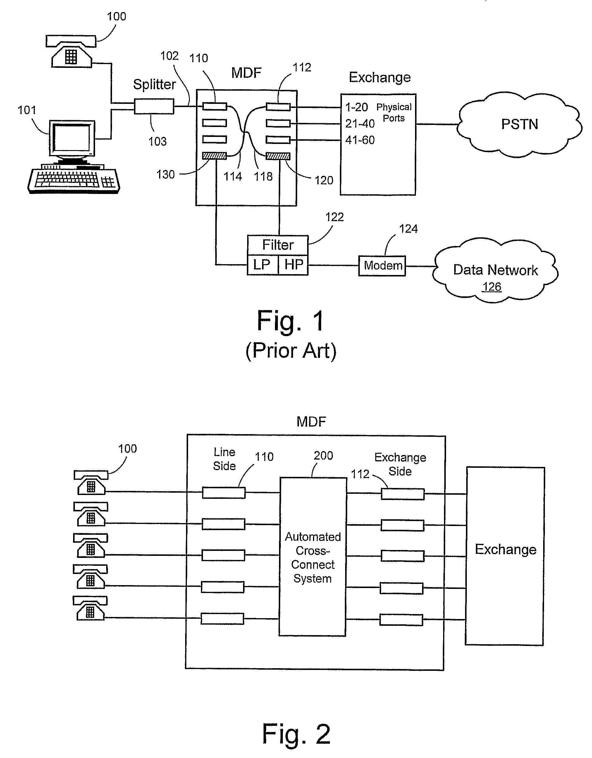
[0010]Briefly described and in accordance with embodiments and related features of the invention, there is provided a method and system for automatically scanning, detecting, and documenting existing jumper wires or metallic cross-connects within a central office main distribution frame (MDF) and non-central office sites such as cabinets and drop points. In an embodiment of the invention, the method includes connecting a plurality of modular sender and receiver means to the connector blocks. Scanning signals are transmitted by the sender means between the lines on the subscriber side and the exchange side, which are received by the receiver means in order to accurately determine which subscriber lines are cross-connected to which lines on the exchange side.
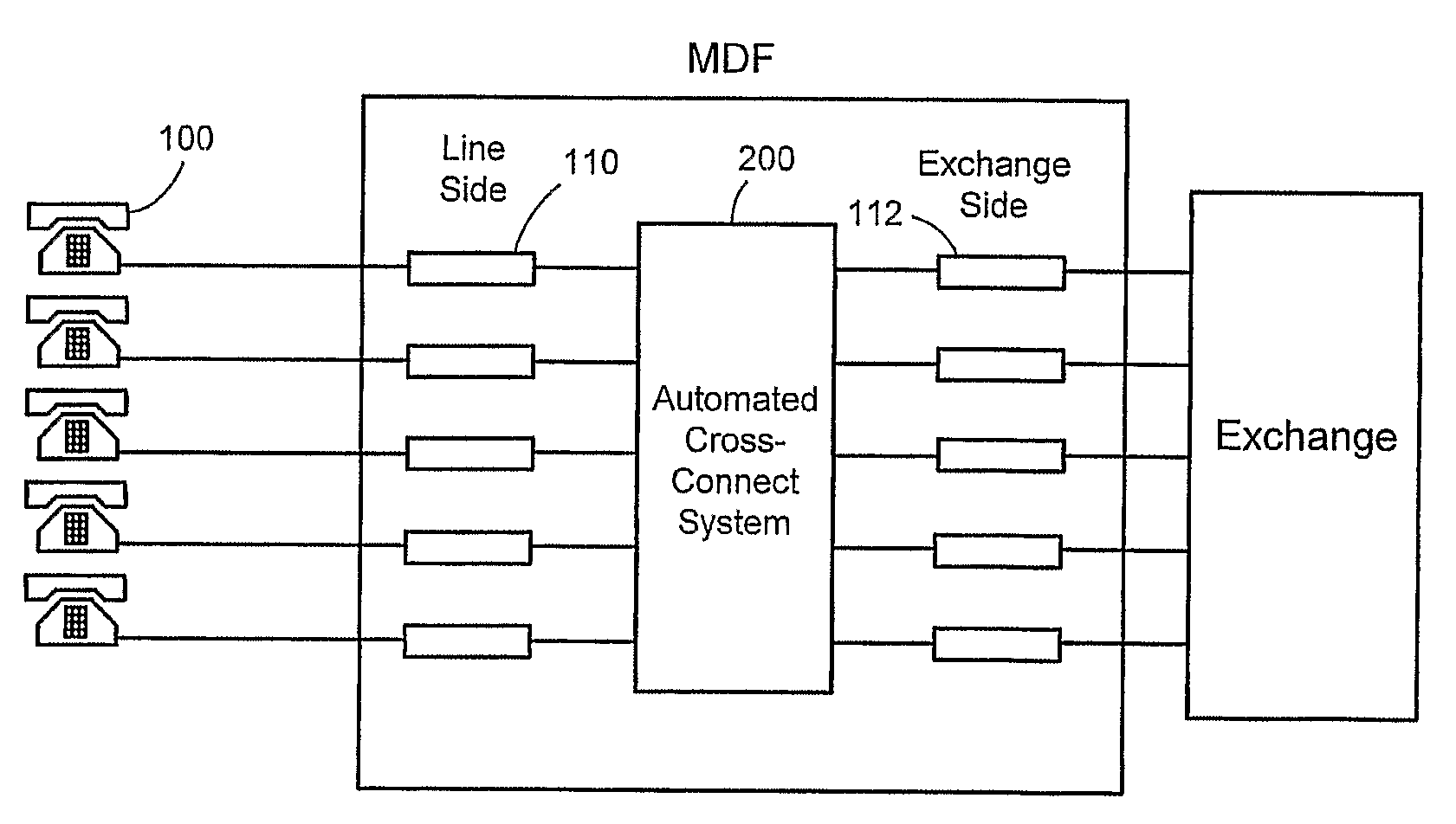
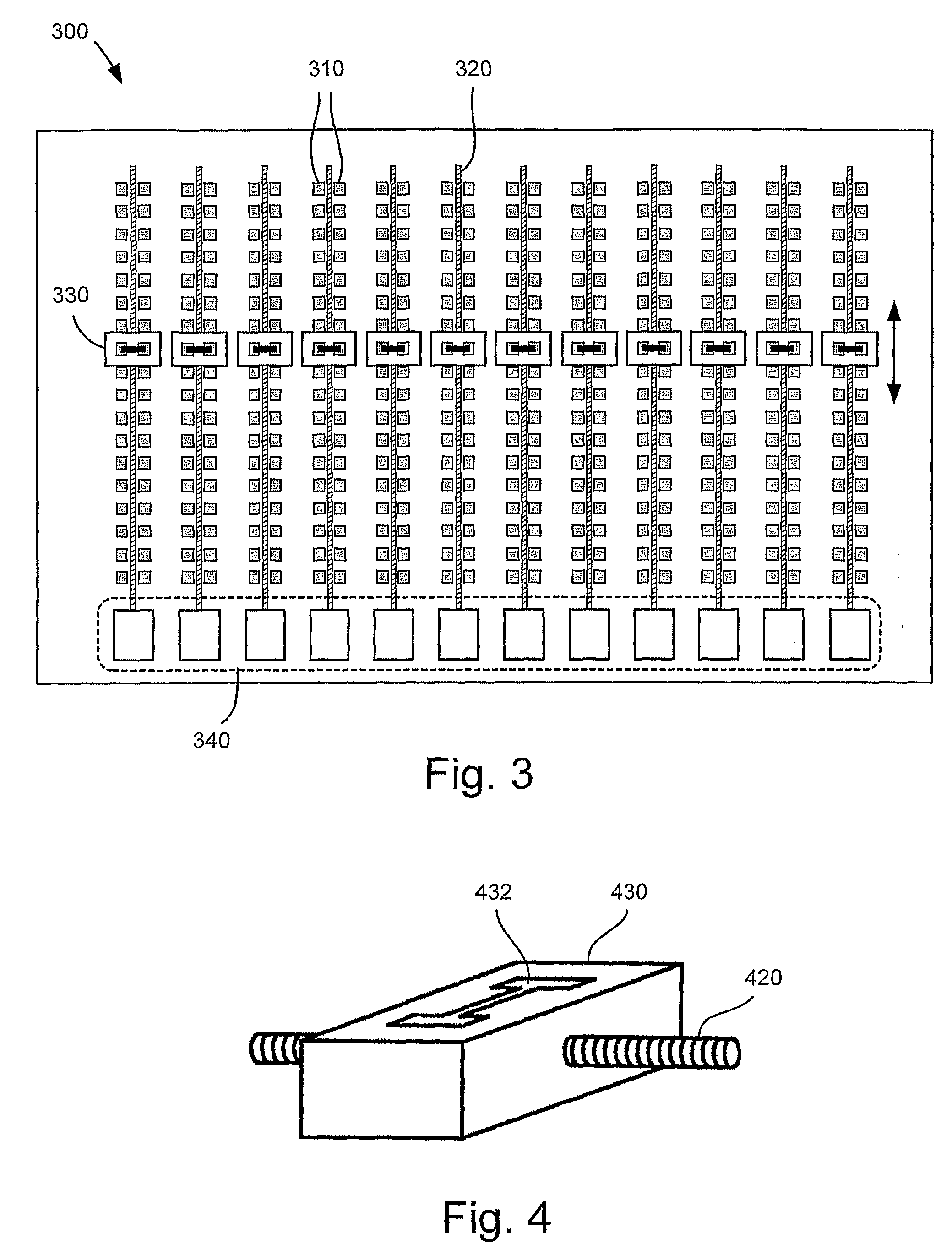
[0011]In another embodiment of the invention, the scanning system is operable in cooperation with an automated cross-connect system installed within the MDF or e.g. the drop point side. The automated cross-connect system comprises modular cross-connect boards, each comprising switch matrix arrangements that enable cross-connects to be established or removed remotely from the central office. The modular cross-connect boards are inserted into or connected to the connector blocks. A plurality of modular sender and receiver means incorporated into the switch matrix arrangements for which scanning for cross-connects is performed by transmitting scanning signals between the lines on the subscriber side and the exchange side. The transmitted signals are received by the receiver means to accurately detect which subscriber lines are cross-connected to which lines on the exchange side. The scanning procedure establishes an accurate line connection database that enables non-intrusive installation of the automated cross-connect system by preserving previous cross-connects. In a further aspect, the combined operation with the automated cross-connect system enables broken cable lines to be repaired within short order by allowing repair crews to reconnect the splintered ends without regard to order such, whereby afterward, the original line connection sequences are restored by automatically modifying the appropriate cross-connects in the central office or in the drop point side.

Problems solved by technology

Management of the copper infrastructure is a highly labour intensive process that results in one of the most significant costs faced by telecommunication providers today.
This manual process is naturally prone to errors since the technician can inadvertently make incorrect cross-connects that can delay activation of new services, or cause a temporary loss of existing services.
Over time as these wires can accumulate to become such a mishmash to the point where a complete rewiring may be required.
When left unchecked, services may be impacted resulting in increased customer dissatisfaction, which would require increased operational expenditures in labor costs to correct the problems.
Another problem is that the tremendous growth in installations of new services such as xDSL are relatively labor intensive.
The new installations and routine service modifications require numerous jumper wires or are added and removed within the MDF by service technicians, which are not always documented properly.
The installations of phone or xDSL service for a subscriber typically involves a relatively high level of manual labor that involve the addition of several jumper wires.
It is readily apparent that the installation of xDSL service made in this way is rather labor intensive since the central office must dispatch a technician to manually install the necessary jumper wires for each subscriber installation.
Another disadvantage of the installation is that must be added connector blocks on both the subscriber and exchange side must accommodate the rerouted jumper wires thereby increasing costs to the operator.
Numerous subscriber installations may require more floor space and eventually make it is necessary to expand the MDF.
When a large number of installations are completed, the amalgamation of jumper wires may result in signalling problems from additional capacitance / resistance that can pick up considerable electromagnetic interference from external sources by cross talk from adjacent active pairs.
All of these effects can disrupt and reduce the performance of the high-speed data service.
It is not unusual to find, after a thorough check, that as many as 10 percent or more of jumper wire connections turn out to be either undocumented or documented incorrectly due to human error that has accrued over many years.
This is also a problem in non-central office sites where jumper cables are used to connect cable pairs in street cabinets and drop points.
An accurate accounting of the connection status has proven to be important to operators because an erroneous database can show that a cable pair is connected which may in reality have been disconnected long ago thereby making it difficult to make efficient use of network infrastructure.
However, a significant disadvantage of these and other prior verification techniques is that they require the presence and attentive input of technicians to set up and monitor the equipment for the task.
As a consequence, the task is generally regarded as a tedious, costly, and often a time consuming exercise.

Method used


Image

  • Method and System for Scanning and Detecting Metallic Cross-Connects
  • Method and System for Scanning and Detecting Metallic Cross-Connects
  • Method and System for Scanning and Detecting Metallic Cross-Connects

Examples


Embodiment Construction

[0024]The scanning, verification and accurate documentation of the current jumper wire and line status in telecom networks is important to operators for a number of other reasons besides routine network optimisation and maintenance. By way of example, an important application for line connection data is to assist in the installation of new equipment such as e.g. an automated cross-connect system installed within a central office MDF. The correct prior knowledge of the line status allows for the possibility of non-intrusive installations, i.e. where the current cross-connects of the lines are maintained after installation of the equipment. An effective technique for quickly performing automated scanning and verification of the jumper configuration within an MDF is to connect the verification equipment directly to the connector blocks and scan the entire set of blocks. This type of connection arrangement is already used in some automated cross-connect systems such as the Nexa™ Automat...


PUM


Abstract

A method and system is disclosed for automatically scanning for and detecting existing jumper wires or metallic cross-connects within a central office main distribution frame (MDF), street cabinet, and drop point sites. In an embodiment of the invention, the method includes connecting a plurality of modular sender and receiver units to the MDF connector blocks. Scanning signals are sent between the lines on the subscriber side and the exchange side that are received by the receivers to accurately determine which subscriber lines are cross-connected to which lines on the exchange side. In a second embodiment, the scanning system is operable in cooperation with an automated cross-connect system installed within the MDF or drop point site. The automated cross-connect system comprises modular switch matrix arrangements that enable cross-connects to be established or removed remotely from the central office. The scanning procedure establishes an accurate line connection database that enables non-intrusive installation of the automated cross-connect system by preserving previous cross-connects. Furthermore, the combined operation with the automated cross-connect system enables cable line repairs to be completed with short order by allowing repair crews to connect the broken lines without regard to order such that the original connection sequences that can be restored by automatically modifying the cross-connects in the central office or in the drop point site.

Description

FIELD OF THE INVENTION[0001]The present invention relates generally to telecommunication networks, and more particularly, to a method and system for scanning to detect jumper wires or metallic cross-connects for non-intrusive equipment installation and cable repair.BACKGROUND OF THE INVENTION[0002]A telecommunication central office houses switching equipment or telephone exchange that is the point to which subscriber home and business lines 120 are connected to the network on what is often called a local loop. Many of these connections to residential subscribers are typically made using a pair of copper wires, also referred to as a twisted pair, that collectively form a large copper network operated by the telecom provider. Within the CO the line connections between the exchange side and the subscriber side are terminated at a main distribution frame (MDF), which is usually the point where cross-connections between the subscriber lines and the exchange lines are made. In addition, s...

Claims


Application Information

Patent Timeline
IPC IPC(8): H04M5/00G01RG01R31/02H04Q1/14H04Q1/24
CPCH04Q1/145H04Q1/023H04Q1/136
Inventor ROOS, STUREOBERG, JOHAN
Owner NORDIA INNOVATION
Learn More