Mounting Device for a Fastening System Trim Elements to Vehicle Body

a technology of fastening system and mounting device, which is applied in the direction of sheet joining, superstructure subunits, ropes and cables for vehicles/pulleys, etc., can solve the problems of increasing costs, slowing down, and increasing costs, so as to reduce the number of different kinds of mounting towers, the effect of simple movemen

Inactive Publication Date: 2008-10-23
ITW AUTOMOTIVE ITALA S R L
View PDF10 Cites 23 Cited by
  • Summary
  • Abstract
  • Description
  • Claims
  • Application Information

AI Technical Summary

Benefits of technology

[0005]It is an object of the present invention to overcome the aforesaid drawbacks by providing a mounting device for fastening systems designed to anchor a finishing element to a body of any kind of vehicles that allow at the same time to make the assembly operation of the finishing element to the vehicle body easier and quicker, and to reduce the production cost of the currently used finishing elements (or at least of the mounting towers thereof), while increasing the reliability thereof and dramatically reducing the possible number of rejects.
[0006]It is also an object of the present invention to provide a mounting device for fastening systems of finishing elements of a vehicle body which allow the fastening systems to be preassembled in their mounting seats on the finishing element side.
[0012]In this manner, the mounting towers may be equipped with standard types of attachment seats, making it possible to simplify the shape of the mounting towers and to dramatically reduce the necessary number of different kind of mounting towers to only one or two.
[0013]Moreover, the assembly of the fastening systems is no more to be carried out directly onto the mounting towers or the finishing elements to be assembled, but can be carried out separately onto the shallow mounting elements, so as to obtain also a preassembly of the fastening systems; then, the unit so created, constituted by the fastening system and the shallow mounting element may be assembled onto the mounting towers with very simple movements only, so allowing for automatic assembly too.
[0014]Last but not the least, strict working tolerances, in order to avoid assembly problems, are necessary solely for obtaining the first coupling means of the shallow mounting elements, so that the production costs of the finishing elements and of the mounting towers (that only have standard types of attachment seats of anyway simple shape) are dramatically reduced due to the possibility to adopt less strict working tolerances. At the same time the number of rejects is reduced and every piece produced is of reliable operation.

Problems solved by technology

The mounting devices described above create not many difficulties in the assembly phase of the fastening system to the mounting tower, which result in slowing down the assembly operations with an increase of costs; moreover they increase the cost of the finishing elements themselves since they require to adopt very strict tolerances in shaping the mounting towers; last but not the least, the complex shape required for the mounting seats to receive the mounting heads of the fastening systems results quite often in creating degassing and shrinkage problems during the molding phase through which the mounting towers and eventually the whole finishing element are obtained; this results in incomplete pieces, so generating a relatively high number of rejects or, worse, molded articles which are not reliable and can break in use.

Method used


Image

  • Mounting Device for a Fastening System Trim Elements to Vehicle Body
  • Mounting Device for a Fastening System Trim Elements to Vehicle Body
  • Mounting Device for a Fastening System Trim Elements to Vehicle Body

Examples


first embodiment

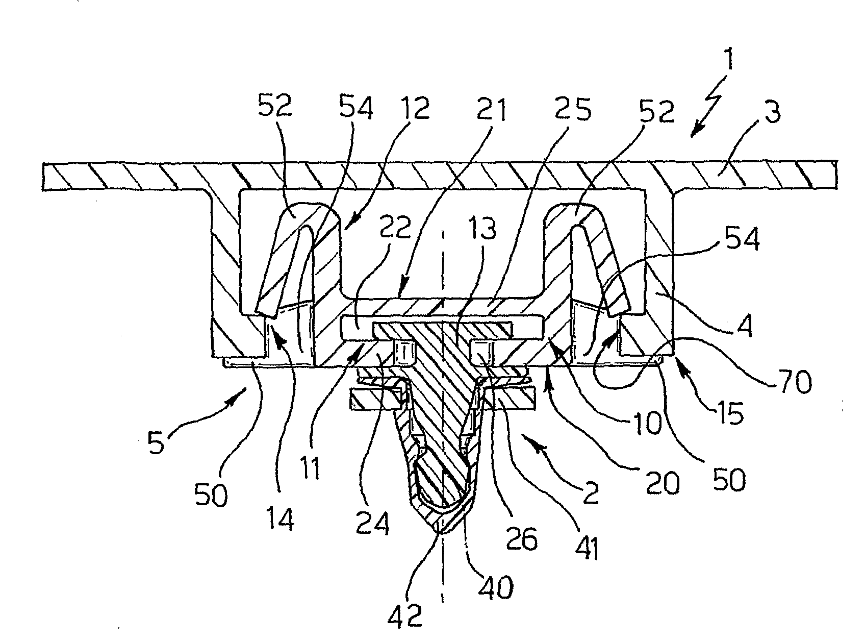
[0025]The shallow mounting element 10 (FIG. 5) consists of an injection molded base plate delimited between a first flat surface 20 and a second flat surface 21, facing in use the selected fastening system 2 and the mounting tower 4, respectively; first coupling means 11 are provided in correspondence with the first flat surface 20, while the second coupling means 12 are provided, in this first embodiment, facing opposite to the flat surface 20.

[0026]Moreover, the base plate 10 is substantially square shaped in a plan view and is provided with a channel shaped through seat 22 laying parallel to said first and second flat surfaces 20 and 21, and delimited between a first flat wall 24 and a second flat wall 25 defining, externally to the base plate 10, the first flat surface 20 and the second flat surface 21, respectively.

[0027]The first coupling means 11 of the shallow mounting element 10 consist of the afore described through seat 22 and of a shaped perforation 26 provided through t...

second embodiment

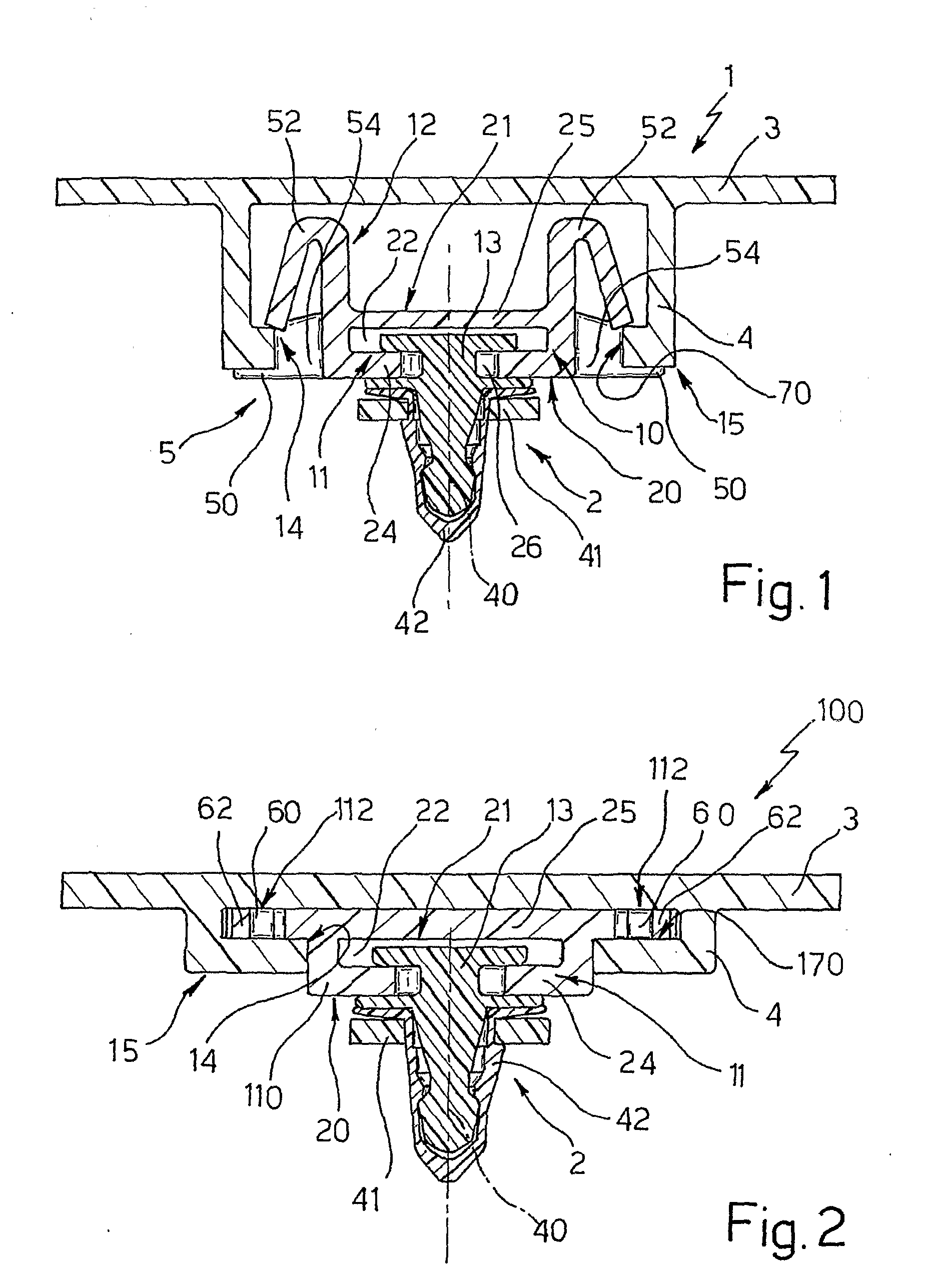
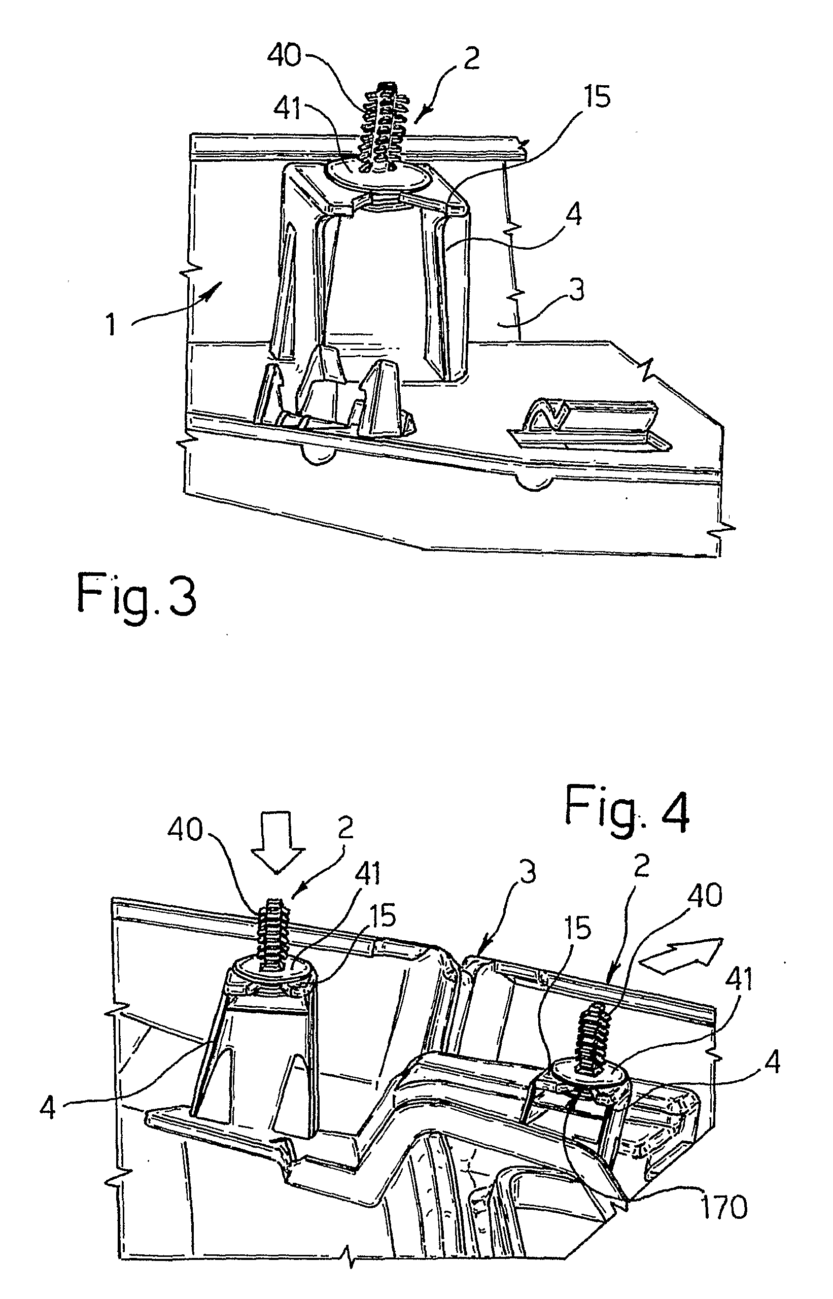
[0030]Shallow mounting element 110, likewise corresponding element 10, is also designed to fit into an attachment seat 14 of prefixed shape provided in the mounting tower 4, on the side thereof opposite to the automotive finishing element 3 to be mounted, in particular at a top end 15 of the mounting tower 4 distant from the finishing element 3; according to this second embodiment, however, seat 14 is shaped to receive in a sliding manner the mounting element 10 in the direction and versus shown by the arrows in FIGS. 2 and 6, namely substantially parallel to the laying plane of the finishing element 3 bearing the mounting tower 4.

[0031]Accordingly, while first coupling means 11 are identical to those as described for the mounting device 1 of FIG. 1, second coupling means 112 are shaped differently, as it will be seen more in detail below, of coupling means 12, in particular coupling means 112 are provided flush with second flat wall 25.

[0032]In both embodiments, namely in both moun...


PUM


Abstract

Mounting device for connecting a fastening system selected from a number of available standard fastening systems to an automotive finishing element like e.g. a door inner panel, a dashboard, etc designed to be fixed to a vehicle body; the mounting device consists in: a standardized mounting tower provided integral with or fixable to said automotive finishing element; and in an intermediate, shallow mounting element designed to be interposed between the fastening system and the mounting tower, having first and second coupling means; said first coupling means being designed to mate with first coupling means of the fastening system designed to provide anchorage with the mounting tower; and said second coupling means being of the snap-on kind and being designed to mate with an attachment seat of prefixed shape for said shallow mounting element provided in said mounting tower, on a side thereof opposite to the automotive finishing element to be mounted.

Description

TECHNICAL FIELD[0001]The present invention relates to a mounting device for connecting a fastening system selected from a number of available standard fastening systems to an automotive finishing element like e.g. a door inner panel or a dashboard, designed to be fixed to a body of a vehicle via said selected fastening system.BACKGROUND ART[0002]It is known in the art that fixing of automotive finishing elements like panels, profiles, dashboards or parts thereof to the elements of the body of vehicle is provided through the use of fastening systems consisting essentially in a toothed pin having a mounting head, a bush and a sealing element interposed there between; the toothed shank of the pin is designed to engage into slots provided in the body elements and to adapt axially there into in order to compensate the misalignments between the finishing element and the body element receiving it due to the working tolerances; the mounting head is designed to fit into a mounting seat provi...

Claims


Application Information

Patent Timeline
Patent Type & Authority Applications(United States)
IPC IPC(8): B60R13/02F16B5/06
CPCB60R13/0206B60R13/0237B60R13/0256B60R16/0215F16B5/0628F16B21/084Y10T24/44026F16B21/09F16B21/16Y10T403/16Y10T24/42Y10T24/309F16B21/086
Inventor GIRODO, FRANCOSERRONE, CALOGERO
Owner ITW AUTOMOTIVE ITALA S R L
Why Eureka
Try Eureka