
Analytical Software Design System

a software design and software technology, applied in the field of analytical software design systems, to achieve the effect of reducing defects, increasing the effectiveness and coverage of component testing

Active Publication Date: 2008-10-23
COCOTEC LTD
View PDF9 Cites 81 Cited by
  • Summary
  • Abstract
  • Description
  • Claims
  • Application Information

AI Technical Summary

Benefits of technology

[0049]An aim of the present invention is to at least substantially reduce the problems that have been described above and to provide a system for software development that when used to develop a software product results in less errors being present in that product, thereby shortening the development time and reducing the costs for generating industrial software which has been fully tested and is free from major defects.

Problems solved by technology

It is widely recognised that such specifications suffer from incompleteness, ambiguity and inconsistencies; in other words, a lack of rigour and precision.
Designs are made by experts in software design and implementation, but whose background domain knowledge is frequently shallow or incomplete.
As a consequence, they will frequently not recognise the shortcomings of the specifications they are working from until well into the implementation of testing phase of a project, if at all.
The behaviour of event driven, embedded software is often extremely complex with much use being made of parallelism and the design must address many issues related to concurrency.
Errors in such designs are common because it is extremely difficult to understand and reason about concurrent systems.
If undetected, such design errors lead to implementation errors that are extremely difficult to detect and diagnose by testing because they tend to be intermittent in their effect and difficult to reproduce.
As a result, it is common for such software to be released with a large number of undiscovered defects and for these to remain undetected for months or even years.
Industrial software development is carried out in a business context and subject to cost and time-to-market constraints.
The scale and complexity of industrial software development puts it beyond the capabilities of single individuals and requires teams of software development experts working together with product and domain specialists.
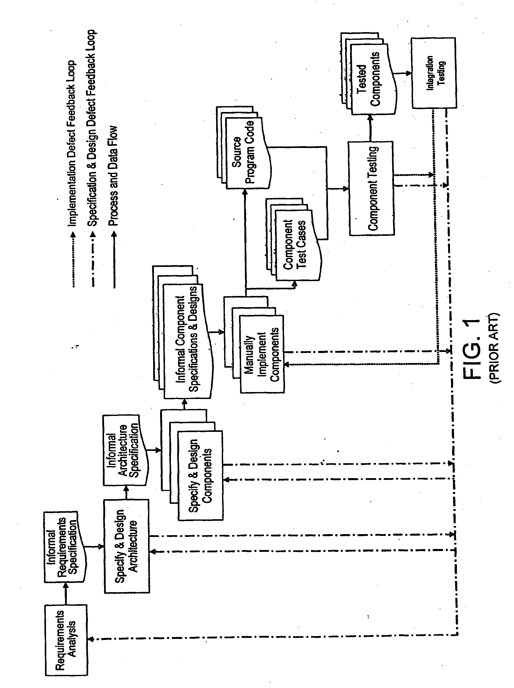
During this step, typically many errors are discovered in the program code.
Some of these are implementation mistakes; others reflect errors made in earlier steps and are defects in the informal requirements, architecture and / or component designs and specifications.
During this step, a class of defects concerned with the interactions between the components are typically encountered for the first time.
Due to issues such as concurrency, these are recognised as being among the most difficult to detect and solve.
Some of these are implementation mistakes; others reflect errors made in earlier steps and are defects in the informal requirements, architecture and / or component designs and specifications.
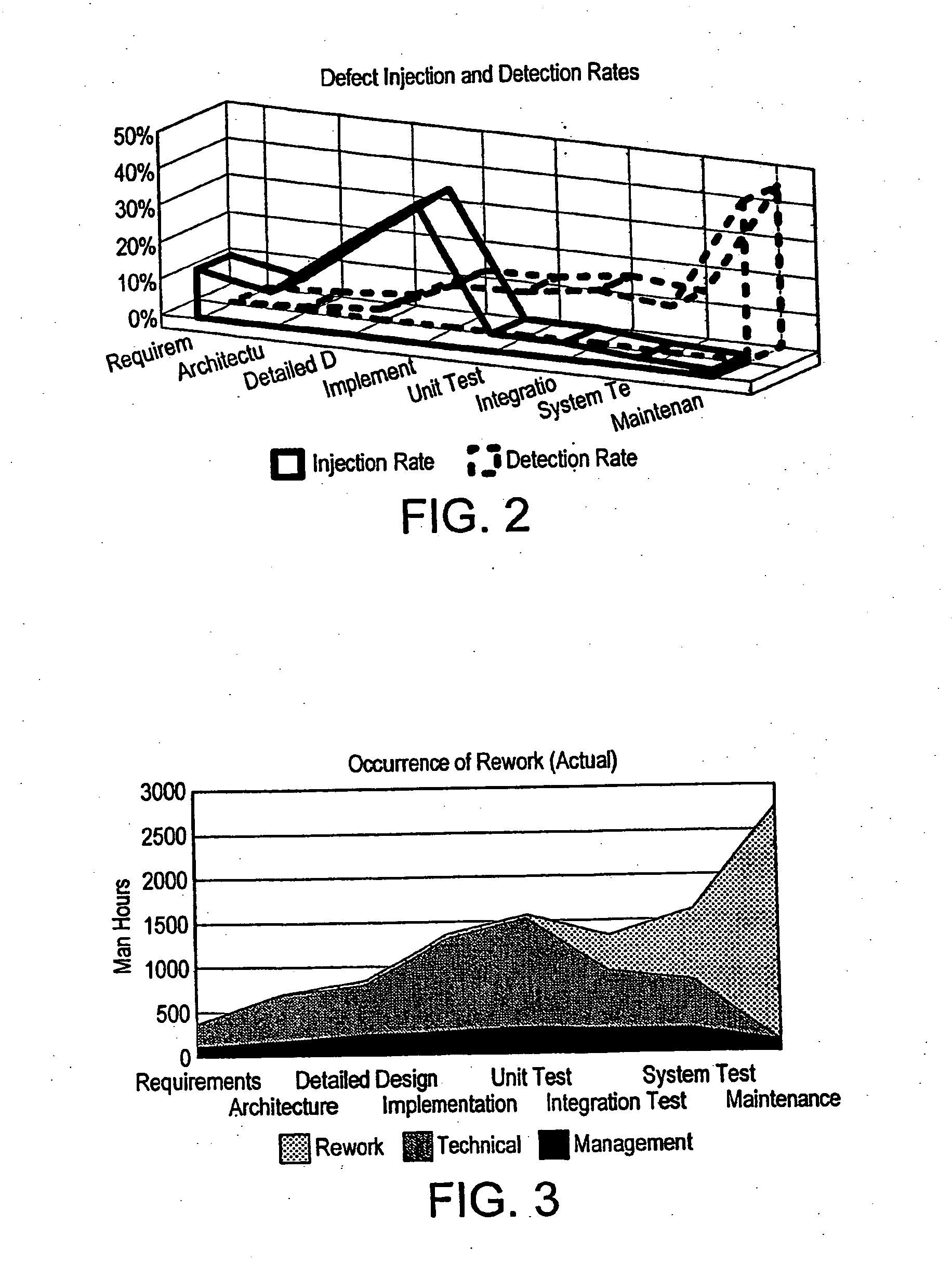
As testing starts, defects are discovered and the amount of rework grows out of control.
As has been shown above there is a problem that errors in specifications and designs are not detected and removed before implementation and as a result, software testing must therefore detect and remove errors that originate in specification and designs, as well as errors of implementation.
For software developed within industry, such a reliance on testing alone leads to unacceptable levels of defects remaining in the software.
Some of the reasons for this, which have been appreciated by industry are summarized as follows:1. Software testing can never be complete and cannot “prove” correctness; and2. Industrial software is too complex to test exhaustively and therefore only a relatively small subset of total functionality can be tested.
Their major weakness is their steadfast refusal to recognise the need for mathematics for specifying and verifying software designs before implementation.
These approaches, although valuable as form of disciplined engineering process, still rely on informal methods of specifying requirements and designs and provide no means for analysing the dynamic behaviour of the proposed designs before implementation.
They also tend to lead to a concentration on the correctness of individual components rather than systems as a whole and do not address the most difficult design issues of concurrency in large systems.
In practice, however, formal methods are hardly ever encountered in the industrial work place.
Lack of integration into software process: There is a communication gap between the formal methods experts on the one hand and the business analysts and domain experts on the other.
Business analysts and domain experts are not generally experts in any specific formal method and cannot participate in the process of developing formal specifications.
Those who understand them don't know enough and those who know enough don't understand them.
Resistance within industry: Software developers and their management are not accustomed to applying mathematics to software development and many lack the necessary education and training to do so.
There is strong resistance among software developers to a formal approach and the costs of doing so are perceived as prohibitive by management.
The use of formal methods requires an attitude shift away from this approach to one focused on defect prevention, a practice common in all other branches of engineering and this change is very difficult to achieve.
The immaturity of formal methods and tools: The formal methods techniques and tools are immature and are not able to cope with industrial scale software developments.
These represent significant technical problems which have not been solved.
They are also serious obstacles to progression because without tooling, all proof obligations must be carried out by hand.
This is both error-prone and infeasible, given the scale of modern software systems being developed.

Method used


Image

  • Analytical Software Design System
  • Analytical Software Design System
  • Analytical Software Design System

Examples


first embodiment

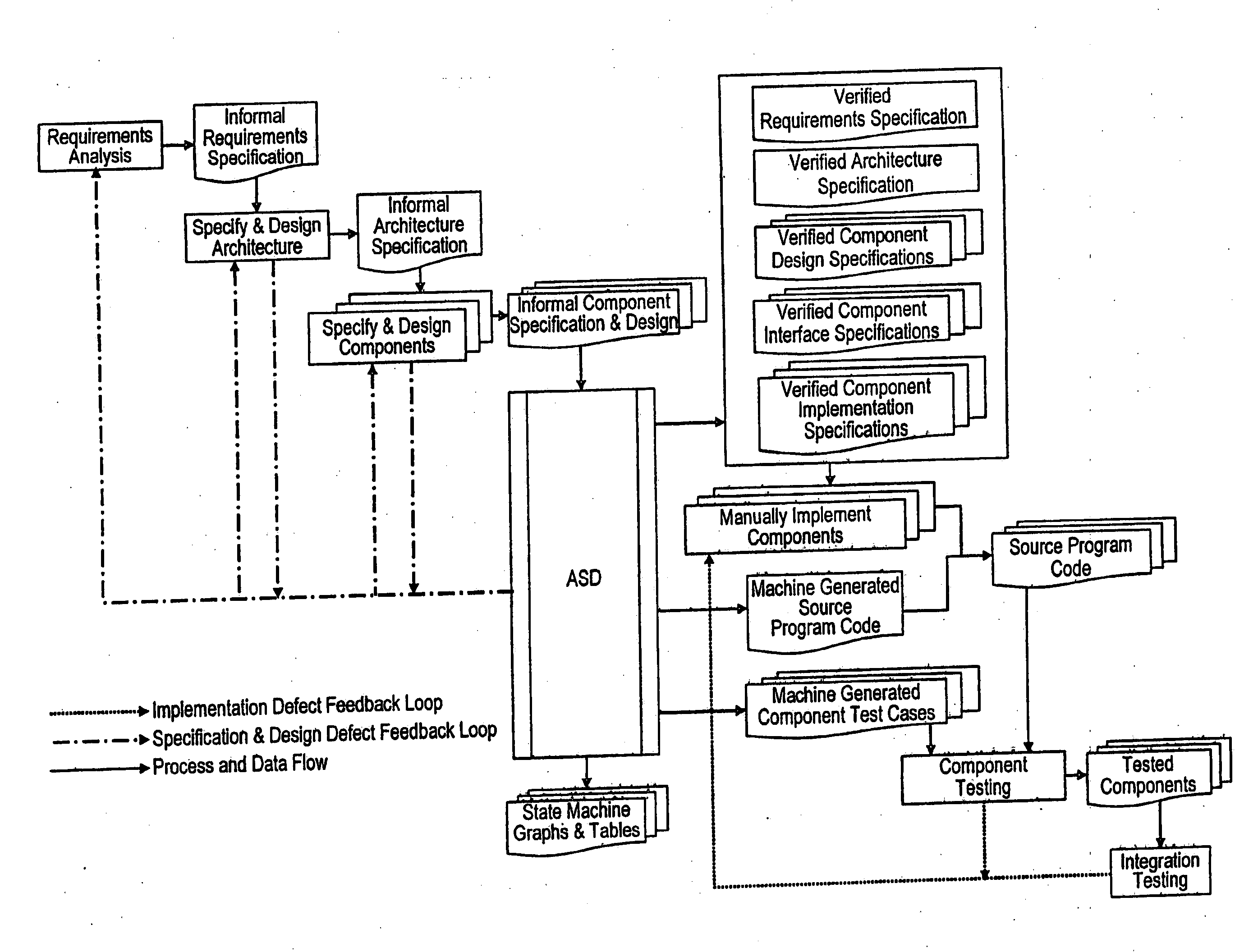
[0143]The Model Generator 106 implements the generic algorithms presented below and automatically generates the necessary mathematical models in a suitable notation. One such mathematical notation is the existing process algebra CSP [Hoa85, Ros98], which is used in the present first embodiment of the present invention.

[0144]The Model Generator 106 forms an important inventive part the ASD System 62 by enabling the output from the sequence-based specification and box structure development described above, to be translated directly into the Mathematical Models 108 needed for subsequent design verification steps. The algorithms used in this translation have been proven mathematically by the present inventor to produce mathematical models 108 that describe exactly the same behaviour as the Sequence-Based Specifications and Component Implementation Specifications from which they are translated. It is this unique link between existing formal techniques and theories that enables them to be...

case 1 (

state(p)=(Res≈Ø)[0182]The process Q (s, r, cj, (y1, . . . , yk)) is defined in terms of the following two cases:[0183]Case 1 (Predicates): The stimulus s is defined in terms of a predicate and therefore takes the form s=s′:p. The resulting CSP process captures the predicate as a guard state (p), defined in terms of the state variables, over the standard sequence of the stimulus s′ event followed by the response r event and leading to the process Pci.[0184]Case 2 (No predicates): The stimulus s does not involve predicates and therefore results in the standard CSP definition as defined in Algorithm 1.[0185]4. The CSP process PBS is then defined as follows:

PBB=Pc0(I1, . . . , Ik) where c0 represents the shortest canonical sequence ⋄ and I1, . . . , Ik are the initial values of each state variable respectively. These initial values are derived directly from the definitions of the specification functions.

Algorithm 3: Translating Under-Specified Black Boxes into CSP

[0186]Predicate functio...

case 1 (defined predicates) : the stimulus s is an abstract stimulus of the form s = s ′ : p , where s ′ is some stimulus in s and p is a defined predicate (i.e.p∈u).the resulting csp process is defined according to step 3 (case 1)

Q(s,r,cj,(y1,…,yk))=state(p)&s′→r→Pcj(y1,…yk)ifs=s′:p,forsomes′∈Sandpredicatep∉U,s′→r→Pcjifs=s′:p,forsomes′∈Sandpredicatep∈U,s→r→Pcj(y1,…,yk)otherwise. where the function state (p) represents the predicate p in terms of the corresponding state variables (as defined in Step 3 of Algorithm 2).[0193]The process Q (s, r, cj, (y1, . . . , yk)) is defined in terms of the following three cases:[0194]Case 1 (Defined predicates): The stimulus s is an abstract stimulus of the form s=s′:p, where s′ is some stimulus in S and p is a defined predicate (i.e. p∉U). The resulting CSP process is defined according to Step 3 (Case 1) of Algorithm 2.[0195]Case 2 (Undefined predicates): The stimulus s is an abstract stimulus of the form s=s′:p, where s′ is some stimulus in S and p is an undefined predicate (i.e. p∈U). The resulting CSP process captures this undefined element by ignoring it (as opposed to constructing a guard) and simply extracting the stimulus s′ as the initial event offered followed...


PUM


Abstract

An analytical software design system arranged to receive informal system design specifications and to convert them into verified design specifications for use in creating source code and carrying out implementation testing of the source code is described. The system comprises a verified black box specification generator arranged to process the received informal system design specifications to create formal specifications; to generate from the formal specifications mathematical models representing the system behaviour; to analyse the mathematical models to determine if they have the required behaviour; to adjust the formal specifications until the required behaviour is achieved; and to derive the required verified design specifications from the mathematical models.

Description

FIELD OF THE INVENTION[0001]The present invention concerns an analytical software design system and more particularly though not exclusively a software design system which is arranged to improve the efficiency and effectiveness of software development within an industrial environment by applying mathematical techniques to specify, model and verify software designs before they are implemented.BACKGROUND OF THE INVENTION[0002]In virtually all recognised branches of engineering, implementations are based on verified designs; that is, the functional requirements of the end product are specified rigorously, mathematical models are constructed to represent these requirements and the proposed designs, and the design models are mathematically verified against the requirements models to ensure that they fulfil their intended function before implementation starts.[0003]Software is not generally developed this way. The majority of software systems are specified by informal requirements specifi...

Claims


Application Information

Patent Timeline
Patent Type & Authority Applications(United States)
IPC IPC(8): G06F9/44
CPCG06F8/10G06F8/24G06F8/20
Inventor BROADFOOT, GUY HAMPSONHOPCROFT, PHILIPPA JANE
Owner COCOTEC LTD
Learn More