Magnetic Convection Heat Circulation Pump

a heat circulation pump and magnetic convection technology, applied in the direction of lighting and heating apparatus, machines using electric/magnetic effects, refrigerating machines, etc., can solve the problems of not being suitable for cooling an object, devices having external heating means only have limited uses, and not being put into commercial use, etc., to reduce the magnitude of saturation magnetization and simple structure

Inactive Publication Date: 2008-10-30
VINCI SA +1
View PDF17 Cites 31 Cited by
  • Summary
  • Abstract
  • Description
  • Claims
  • Application Information

AI Technical Summary

Benefits of technology

[0008]In the magnetic convection heat circulation pump of the present invention, the magnetic fluid in the fluid circulation path receives heat in said heat receiving section to decrease the magnitude of saturation magnetization in response to the magnetic field applied to the fluid circulation path and tends to displace in the fluid circulation path toward the heat discharging section creating magnetic convection. Therefore, the pump is simple in structure, operates as far as a temperature differential is present between the heat receiving and discharging sections, and has an advantage of transferring a large quantity of heat by circulating the magnetic fluid as fast as possible using a large temperature differential.

Problems solved by technology

Heat transfer devices utilizing magnetic convection of a magnetic fluid exhibiting temperature-dependent saturation magnetization have long been known, but they have not been put into commercial practice for several reasons including the difficulty of producing of a magnetic fluid having uniform distribution of finely divided ferromagnetic particles of little or no residual magnetism.
However, the devices having external heating means have only limited uses and are not suitable for cooling an object.
However, the system is complicated and expensive because of the controller and requisite wiring.

Method used


Image

  • Magnetic Convection Heat Circulation Pump
  • Magnetic Convection Heat Circulation Pump
  • Magnetic Convection Heat Circulation Pump

Examples


Embodiment Construction

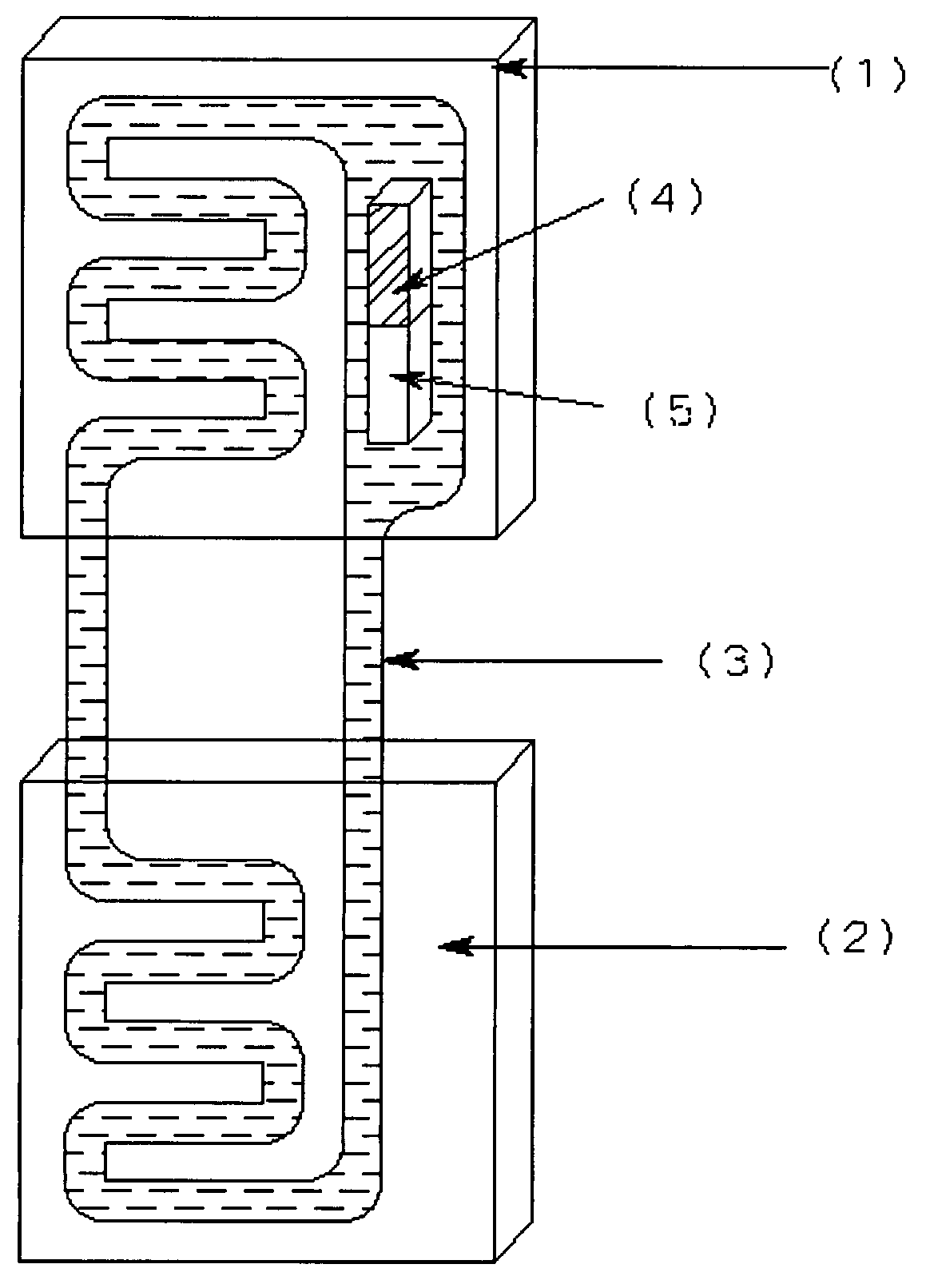
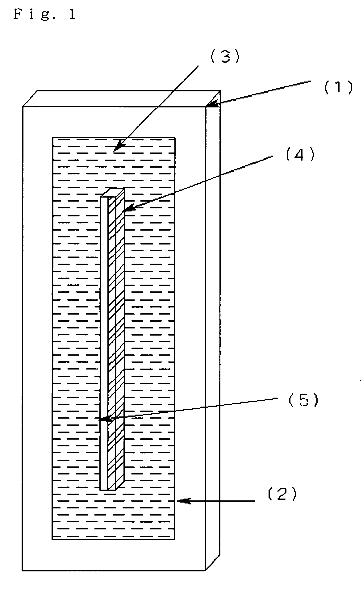
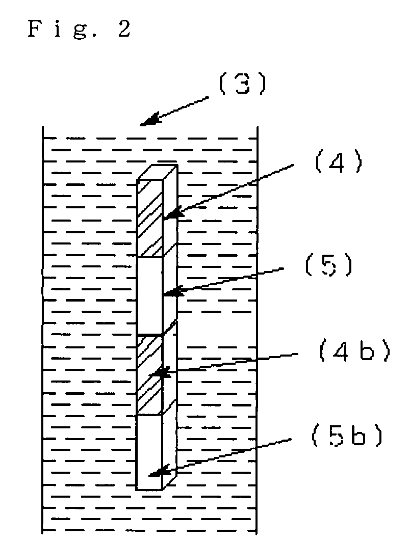
[0018]According to the present invention, one or more magnets are disposed in the circulation path of a magnetic fluid. Alternatively part of the fluid circulation path may be defined by one or more magnets. Preferably, the magnets are plated with nickel or the like on the surfaces directly contacting the magnetic fluid and the plated surfaces are coated with a surfactant having the same ionic charge as the surfactant used for coating the particulate ferromagnetic material dispersed in the magnetic fluid. The above treatment allows direct application of the magnetic field to the magnetic fluid with reduced flow resistance.

[0019]Preferably, a ferromagnetic material having strongly temperature-dependent saturation magnetization such as a ferrite comprising manganese and zinc is employed as the particulate ferromagnetic material of the magnetic fluid. The particulate ferromagnetic material has an average particle size less than about 10 nm, preferably less than 6 nm, most preferably ab...


PUM


Abstract

A magnetic convection heat circulation pump, wherein magnets are disposed inside a magnetic field flow passage for passing a magnetic fluid therein or on a part of the inner wall surface of a circulation flow passage in a magnetic pump thermally joined to a heat receiving part. The magnetic fluid is driven since a magnetic force is directly applied to the magnetic fluid and a large temperature gradient is produced between the heat receiving part and the magnetic pump due to a difference between a heat quantity transferred from the heat receiving part indirectly to the magnetic pump and the heat quantity of the magnetic fluid led into the magnetic pump.

Description

TECHNICAL FIELD[0001]The present invention relates to a device for transferring heat energy. More particularly, it relates to a magnetic convection heat circulation pump which utilizes a magnetic fluid exhibiting temperature-dependent saturation magnetization.[0002]Heat transfer devices utilizing magnetic convection of a magnetic fluid exhibiting temperature-dependent saturation magnetization have long been known, but they have not been put into commercial practice for several reasons including the difficulty of producing of a magnetic fluid having uniform distribution of finely divided ferromagnetic particles of little or no residual magnetism.[0003]Attempts have been made to obviate the above problems in recent years. For example, JP 10 / 231814A discloses a fluid flow control device utilizing a paramagnetic gas exhibiting temperature-dependent saturation magnetization, while JP 3 / 102804A discloses a heat transfer device utilizing a magnetic fluid exhibiting temperature-dependent sa...

Claims


Application Information

Patent Timeline
Patent Type & Authority Applications(United States)
IPC IPC(8): F25B21/02
CPCF28D15/0266F28F23/00F28F2250/08
Inventor NAKASUKA, SHINICHISAHARA, HIRONORIHIGASHI, KENJI
Owner VINCI SA
Why Eureka
Try Eureka