[0005]Therefore, according to example embodiments of the present invention, a sheathed element glow plug for a self-igniting
internal combustion engine has an integrated combustion
chamber pressure sensor and which avoids the disadvantages of the devices as described above. In particular, the sheathed element glow plug permits the fluctuations in the sensor pre-tension, caused by temperature, and the mechanical friction of individual components of the sheathed element glow plug during operation, which, as described above, may result in problems in certain conventional devices to be minimized. The sheathed element glow plug for a self-igniting internal combustion engine has a
heating element, a glow plug housing, and a glow plug axis. Example embodiments of the present invention provide a fixed and, e.g., fully gas-tight connection established between the glow plug housing and the heating element. The functionality of the combustion chamber
pressure sensor is achieved through the flexibility of the glow plug housing in the area between its combustion chamber-side end and its end screwed into the
cylinder head.
[0009]The flexibility area may have an undulation or a
bellows having at least one fold turned to the inside of the glow plug housing or to the outside. Alternatively or additionally, the at least one flexibility area may also have at least one area having a small wall thickness of the glow plug housing, in particular a wall thickness that is less than in the adjacent areas of the glow plug housing or than in the entire rest of the glow plug housing. This arrangement also results in a reduced rigidity of the glow plug housing parallel to the glow plug axis in the flexibility area. Alternatively or additionally, an elastic element, for example, a spring element, e.g., a
helical spring or a similar spring element or also an elastic element made of metallic material or a plastic, for example, an
elastomer, may also be used, which ensures flexibility in the at least one flexibility area parallel to the glow plug axis. In general, an element, e.g., a material, having a
low modulus of elasticity may also be used. A
low modulus of elasticity is to be understood here in particular as a modulus of elasticity which is smaller than the moduli of elasticity of the surrounding wall areas or of the entire glow plug housing.
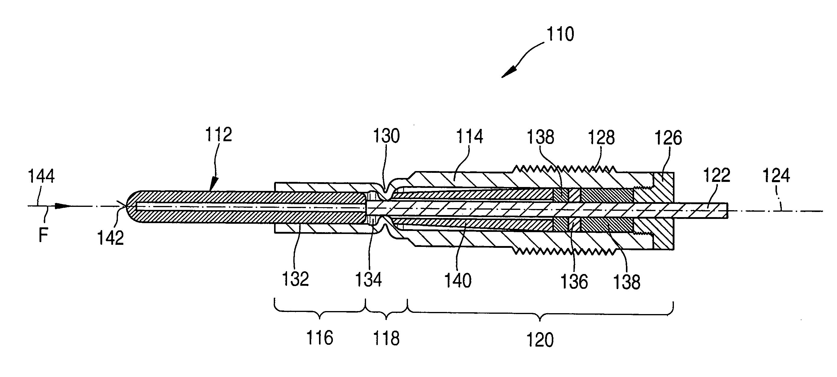
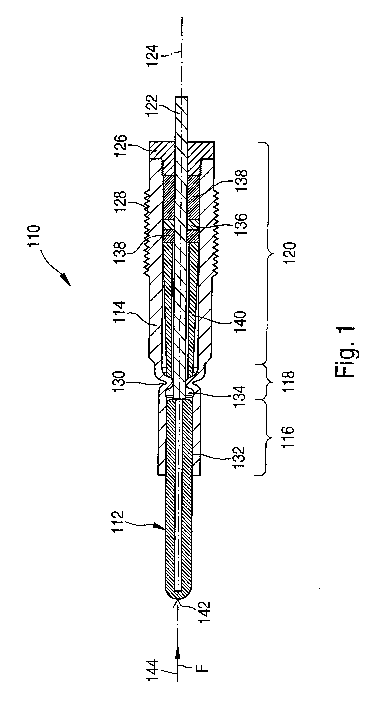
[0012]The at least one force transmission element is supported, e.g., as far to the front toward the combustion chamber as possible by the glow plug housing or even directly by the heating element. On its opposite end, the at least one force transmission element is supported, directly or indirectly, by the at least one force measuring element, so that a force is transmissible, as described above, from the at least one heating element to the at least one force measuring element. When installed, the glow plug housing may be tensile stressed and the at least one force transmission element may be compression stressed. This stressing (pre-tension) may take place, for example, with the aid of a thread or a caulking of the at least one force measuring element in the glow plug housing, e.g., in the housing body. An
advantage of the flexibility area is that different thermal expansions of the glow plug housing and of the at least one force transmission element are compensated by the flexibility of the housing in the area of the at least one flexibility area and thus cause only a relatively small fluctuation of the pre-tension force exerted on the at least one force measuring element. This results in better
signal quality and avoids
signal correction in the different operating states of the internal combustion engine which usually also result in corresponding temperature fluctuations. Fluctuations in the outside temperatures are also at least partially compensated. In rest operation of the internal combustion engine, e.g., no axial forces act on the heating element, the connection between heating element and glow plug housing being unstressed in. rest operation.
[0013]As described above, one end of the at least one force transmission element may be supported directly or indirectly (for example, via an intermediary element) by the at least one force measuring element. The other end of the transmission element may be supported directly by the heating element, for example, or, alternatively or additionally, by the at least one flexibility area. For example, the at least one force transmission element may be supported by an undulation of the flexibility area directed toward the inside of the glow plug housing. Alternatively or additionally, the at least one force measuring element may also be supported by an area of the glow plug housing which is situated between the at least one flexibility area and the at least one heating element. For example, for this purpose, at least one additional supporting element may be used, which is used for supporting the at least one force transmission element on the glow plug housing in the area between the flexibility area and the heating element. For example, a circular disk may be used, whose periphery is connected, for example, screwed or caulked, to the wall of the glow plug housing. These options for supporting the at least one force transmission element cause the force transmission element to be supported, as described above, as far to the front toward the combustion chamber as possible, causing minimum tensions to occur in the rigid area of the glow plug housing which faces away from the combustion chamber. The at least one flexibility area may be directly adjacent to the heating element in the glow plug housing or, alternatively or additionally, a gap between the heating element and the flexibility area is additionally filled with a filling material. The effect of this refinement is that no excessive flexibility occurs prior to the introduction of force from the heating element to the at least one force transmission element. For this purpose, the filling material may be, for example, a highly rigid and, e.g., poorly heat-conducting material. This refinement causes the most direct force transmission possible from the heating element to the at least one force transmission element, which further improves the force
transmission function of the combustion chamber pressure onto the at least one force measuring element.
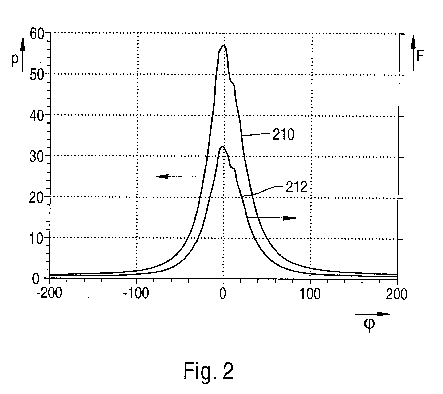
[0015]The sheathed element glow plug having an integrated combustion chamber pressure sensor has numerous advantages compared to conventional devices. One important
advantage is the independence of the combustion chamber pressure signal from the
operating temperature of the internal combustion engine because temperature fluctuations and related differing material expansions are compensated in an optimum manner. Another
advantage is that an almost
constant force transmission function is ensured. This means, e.g., that the combustion chamber pressure is transmitted to the at least one force measuring element in an identical or similar manner in almost all ranges of the combustion chamber pressure and thus in almost all operating ranges of the internal combustion engine. The force transmission factor by which the electrical signal of the at least one force measuring element is to be multiplied to deduce the actual combustion chamber pressure from this signal is thus largely independent of the operating state of the internal combustion engine. Additional corrections which involve complex calculations and must include, for example, appropriate correction functions, etc., may thus be avoided. The electrical signal of the at least one force measuring element may thus be used directly or after only minor electronic
processing for a corresponding engine control, for example, for engine control based on the combustion chamber pressure signal.

