Radio Receiver, Radio Transmitter, and Hearing Aid

a radio transmitter and receiver technology, applied in the field of radio receivers, can solve the problems of complete breakdown of the radio link, all radio systems, and the lowest power consumption possible, and achieve the effect of better reception

Active Publication Date: 2008-10-30
NXP BV
View PDF11 Cites 29 Cited by
  • Summary
  • Abstract
  • Description
  • Claims
  • Application Information

AI Technical Summary

Benefits of technology

[0004]It is an object of the present invention to provide a receiver which provides a better

Problems solved by technology

In general, all radio systems suffer from one common problem, namely how to obtain as wide as possible a radio range at the lowest possible power consumption.
If the distance between sender and receiver is too great or if the radio power is too low, errors in the data transmission may occur, possibly even resulting in a complete breakdown of a radio link.
However, the use of such an antenna furthermore results in correspondingly bu

Method used


Image

  • Radio Receiver, Radio Transmitter, and Hearing Aid
  • Radio Receiver, Radio Transmitter, and Hearing Aid
  • Radio Receiver, Radio Transmitter, and Hearing Aid

Examples


Embodiment Construction

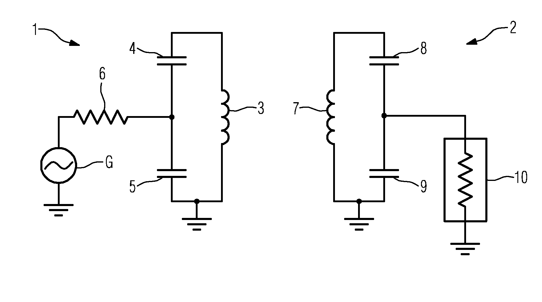
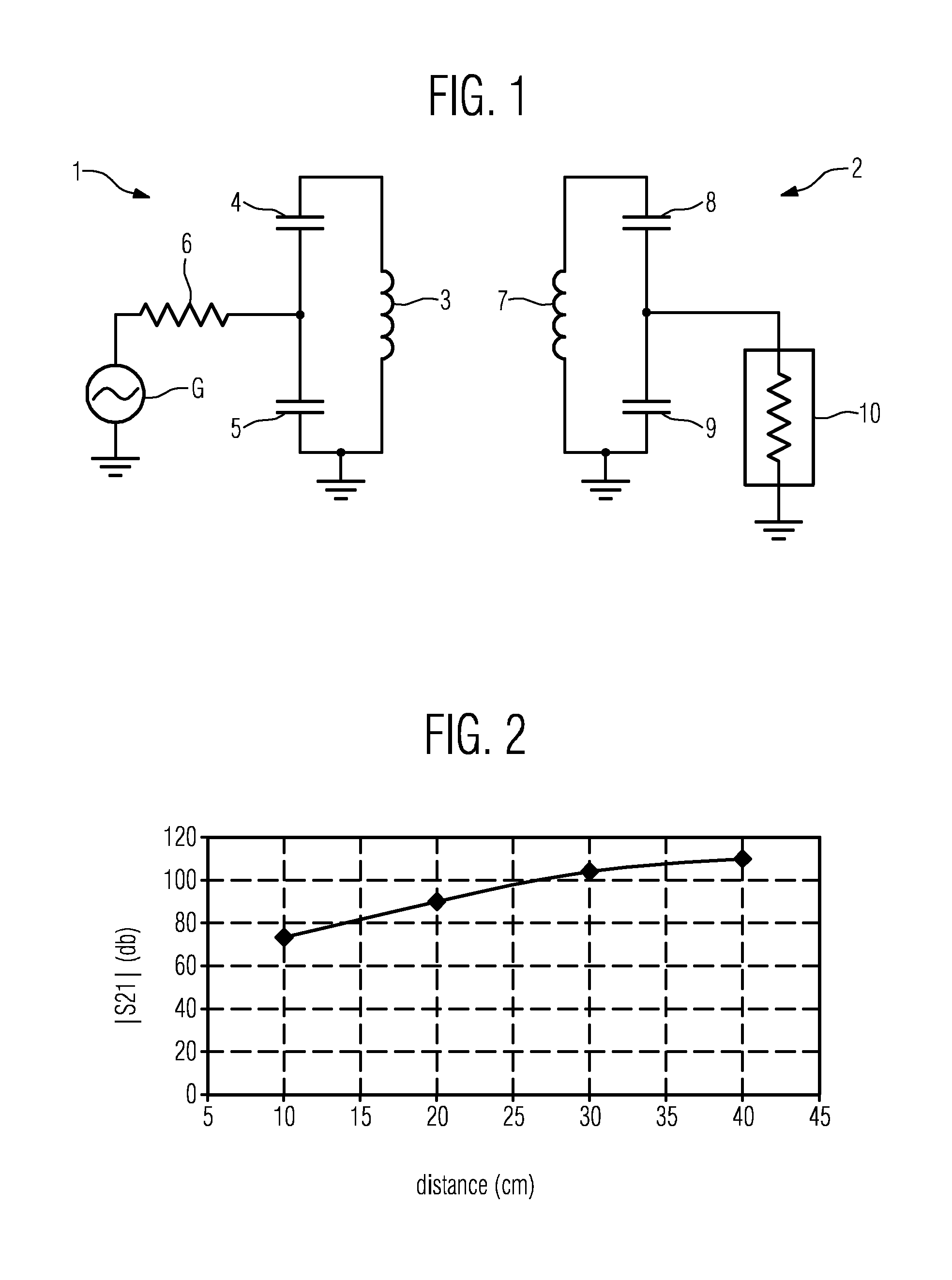
[0023]FIG. 1 shows the circuit diagram of a transmitter 1, which transmits a signal to a receiver 2. The transmitter 1 and the receiver 2 are set up to be magnetically coupled, i.e. the receiver 2 and the transmitter 1 are spaced apart within a relatively short distance.

[0024]The transmitter 1 comprises a signal generator G that generates a signal. This signal is applied to a tuned LC circuit consisting of a coil 3 and two capacitors 4, 5. The coil 3 serves as an antenna of the transmitter 1. The transmitter 1 further comprises an output resistor 6.

[0025]The signal generated by the generator G causes a current with a given frequency to flow through the coil 3. Accordingly, the current through the coil 3 generates a magnetic field of a certain wavelength corresponding to the frequency of the current flowing through the coil 3.

[0026]The receiver 2 comprises a coil 7 and two capacitors 8, 9. The coil 7 of the receiver 2 operates as an antenna of the receiver 2. The coil 7 may be an air...


PUM


Abstract

A receiver (30) with an antenna circuit is disclosed, which antenna circuit comprises a coil (31) and either a monopole (35) or a dipole connected to the coil (31). The antenna circuit captures a signal with a wavelength transmitted by a transmitter (1). The coil (31) captures the signal and generates therefrom a current having a frequency corresponding to the wavelength. The coil (31) is dimensioned such that the current is distributed uniformly within the coil (31) at each point in time. Preferably, the monopole (35) or a leg of the dipole has a length corresponding to less than 5% of the wavelength. The invention further relates to a radio transmitter of the same kind. Finally, the invention relates to an RFID tag, a smart card, a mobile device, and a hearing aid, each comprising an inventive receiver (30) and/or an inventive transmitter.

Description

FIELD OF THE INVENTION[0001]The invention relates to a radio receiver with an antenna circuit which captures a signal with a wavelength transmitted by a transmitter; said antenna circuit comprising a coil generating, by capturing said signal, a current having a frequency corresponding to said wavelength. The invention furthermore relates to a radio transmitter of the same kind. Finally, the invention relates to an RFID tag, a smart card, a mobile device, and a hearing aid, each comprising an inventive receiver and / or an inventive transmitter.BACKGROUND OF THE INVENTION[0002]A variety of radio systems are available nowadays for transmitting signals wirelessly over a very short distance of less than approximately 1.5 m. Examples of such systems are Bluetooth, NFC (Near Field Communication) and WLAN (Wireless Local Area Network), etc. In general, all radio systems suffer from one common problem, namely how to obtain as wide as possible a radio range at the lowest possible power consump...

Claims


Application Information

Patent Timeline
IPC IPC(8): H01Q21/00H04R25/00
CPCH01Q7/00H01Q9/20H01Q9/30H01Q21/29
Inventor KERSELAERS, ANTHONYELSEN, FELIX
Owner NXP BV
Why Eureka
Try Eureka