System and method of density and effective atomic number imaging

a density and effective atomic number technology, applied in the field of diagnostic imaging, can solve the problems of high noise of typical techniques, significant formulation error, and unstable existing algorithms for the decomposition of energy sensitive data into density and effective z, and achieve the effect of improving accuracy and/or precision

Inactive Publication Date: 2008-11-06
GENERAL ELECTRIC CO
View PDF5 Cites 30 Cited by
  • Summary
  • Abstract
  • Description
  • Claims
  • Application Information

AI Technical Summary

Benefits of technology

[0009]Therefore, it would be desirable to design a system and method that enhances accuracy a

Problems solved by technology

The resulting error in the formulation is significant when very small differences in atomic number are sought such as where delta Z is a fraction of an atomic number.
Furthermore, existing algori

Method used


Image

  • System and method of density and effective atomic number imaging
  • System and method of density and effective atomic number imaging
  • System and method of density and effective atomic number imaging

Examples


Embodiment Construction

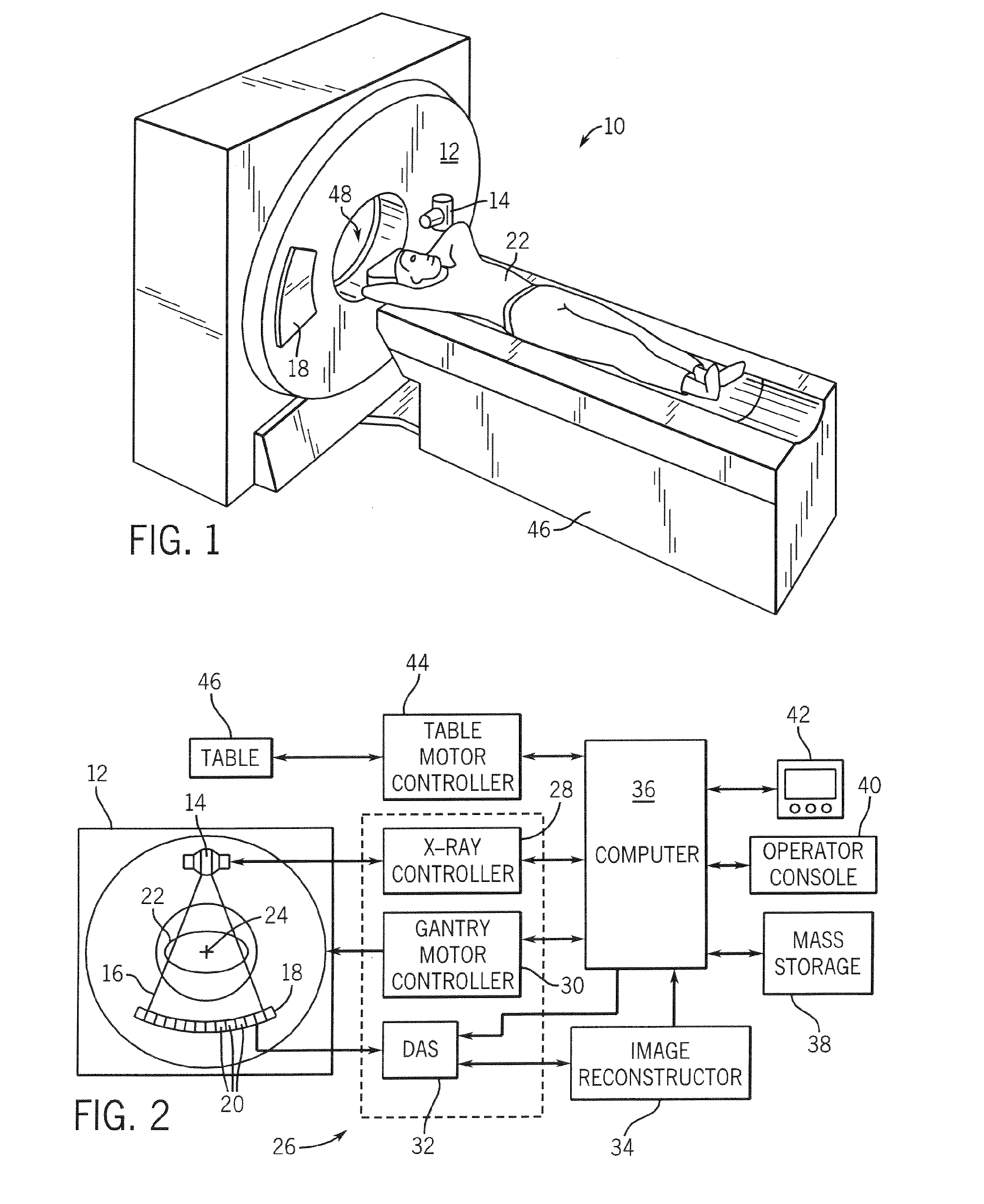
[0021]Exemplary diagnostics devices comprise x-ray systems, magnetic resonance (MR) systems, ultrasound systems, computed tomography (CT) systems, positron emission tomography (PET) systems, ultrasound, nuclear medicine, and other types of imaging systems. Exemplary applications of x-ray sources comprise imaging, medical, security, and industrial inspection applications. However, it will be appreciated by those skilled in the art that an exemplary implementation is applicable for use with single-slice or other multi-slice configurations. Moreover, an exemplary implementation is employable for the detection and conversion of x-rays. However, one skilled in the art will further appreciate that an exemplary implementation is employable for the detection and conversion of other high frequency electromagnetic energy. An exemplary implementation is employable with a “third generation” CT scanner and / or other CT systems.

[0022]Referring to FIGS. 1 and 2, a CT imaging system 10 is shown as i...


PUM


Abstract

A system and method of density and effective atomic number imaging include a computer programmed to acquire projection data from the detector of an unknown material at the time of projection data acquisition. The computer is also programmed to generate a density image for the unknown material based on a calibration of two or more known basis materials and to generate an effective atomic number (Z) for the unknown material based on the calibration of two or more known basis materials and based on a function arctan of a ratio of atomic numbers of the two or more known basis materials. The density and effective atomic number images are stored to a computer readable storage medium.

Description

BACKGROUND OF THE INVENTION[0001]The present invention relates generally to diagnostic imaging and, more particularly, to a method and apparatus of basis material decomposition and representation of diagnostic imaging data.[0002]Exemplary diagnostics devices comprise x-ray systems, magnetic resonance (MR) systems, ultrasound systems, computed tomography (CT) systems, positron emission tomography (PET) systems, ultrasound, nuclear medicine, and other types of imaging systems. Typically, in CT imaging systems, an x-ray source emits a fan-shaped beam toward a subject or object, such as a patient or a piece of luggage. Hereinafter, the terms “subject” and “object” shall include anything capable of being imaged. The beam, after being attenuated by the subject, impinges upon an array of radiation detectors. The intensity of the attenuated beam radiation received at the detector array is typically dependent upon the attenuation of the x-ray beam by the subject. Each detector element of the...

Claims


Application Information

Patent Timeline
IPC IPC(8): H05G1/26
CPCA61B6/032A61B6/4241A61B6/481A61B6/505A61B6/583
Inventor WALTER, DEBORAH JOYWU, XIAOYETKACZYK, JOHN ERICDU, YANFENG
Owner GENERAL ELECTRIC CO
Why Eureka
Try Eureka