Eureka AIR delivers breakthrough ideas for toughest innovation challenges, trusted by R&D personnel around the world.

Cap removal apparatus and cap removal method for vacuum blood collection tubes

Active Publication Date: 2008-11-13
IDS CO LTD
View PDF5 Cites 15 Cited by
  • Summary
  • Abstract
  • Description
  • Claims
  • Application Information

AI Technical Summary

Benefits of technology

[0008]The present invention has been made in consideration of these circumstances, and its object is to provide a cap removal apparatus and a cap removal method for vacuum blood collection tubes, capable of easily preventing blood from splashing out of the collection tubes when the collection tubes are uncapped, thereby solving the problem of contamination.

Problems solved by technology

Accordingly, the surface level of the blood in the collection tube is depressed by the atmospheric pressure, so that the blood splashes out of the collection tube and adheres to peripheral devices or adjoining collection tubes, thereby causing contamination.

Method used


Image

  • Cap removal apparatus and cap removal method for vacuum blood collection tubes
  • Cap removal apparatus and cap removal method for vacuum blood collection tubes
  • Cap removal apparatus and cap removal method for vacuum blood collection tubes

Examples


Embodiment Construction

[0018]An embodiment of the present invention will now be described with reference to the accompanying drawings.

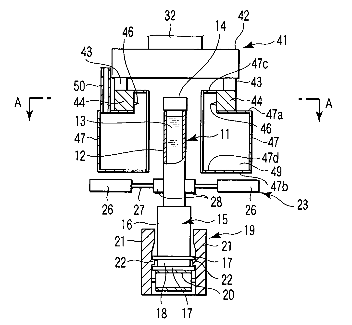
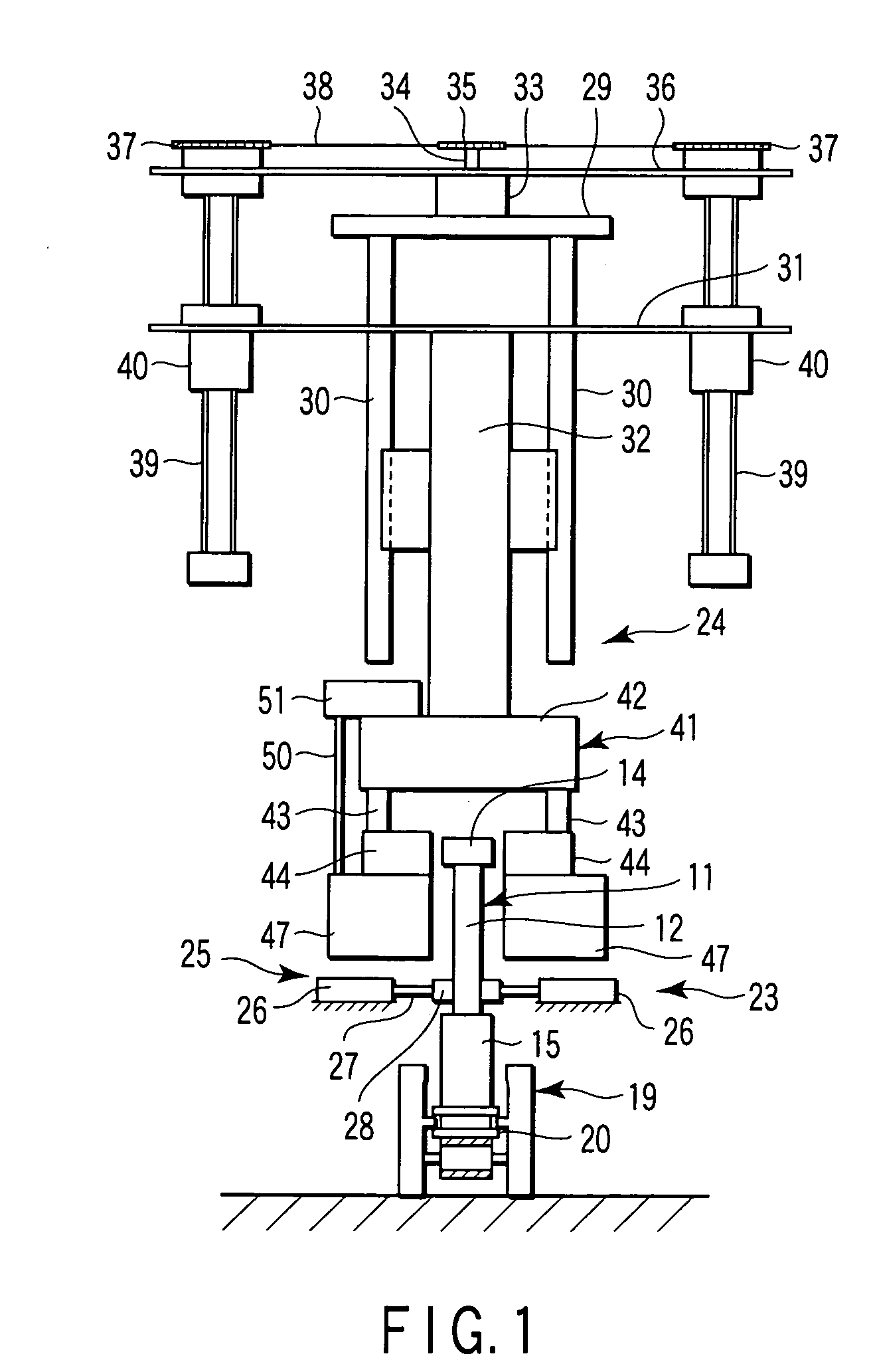
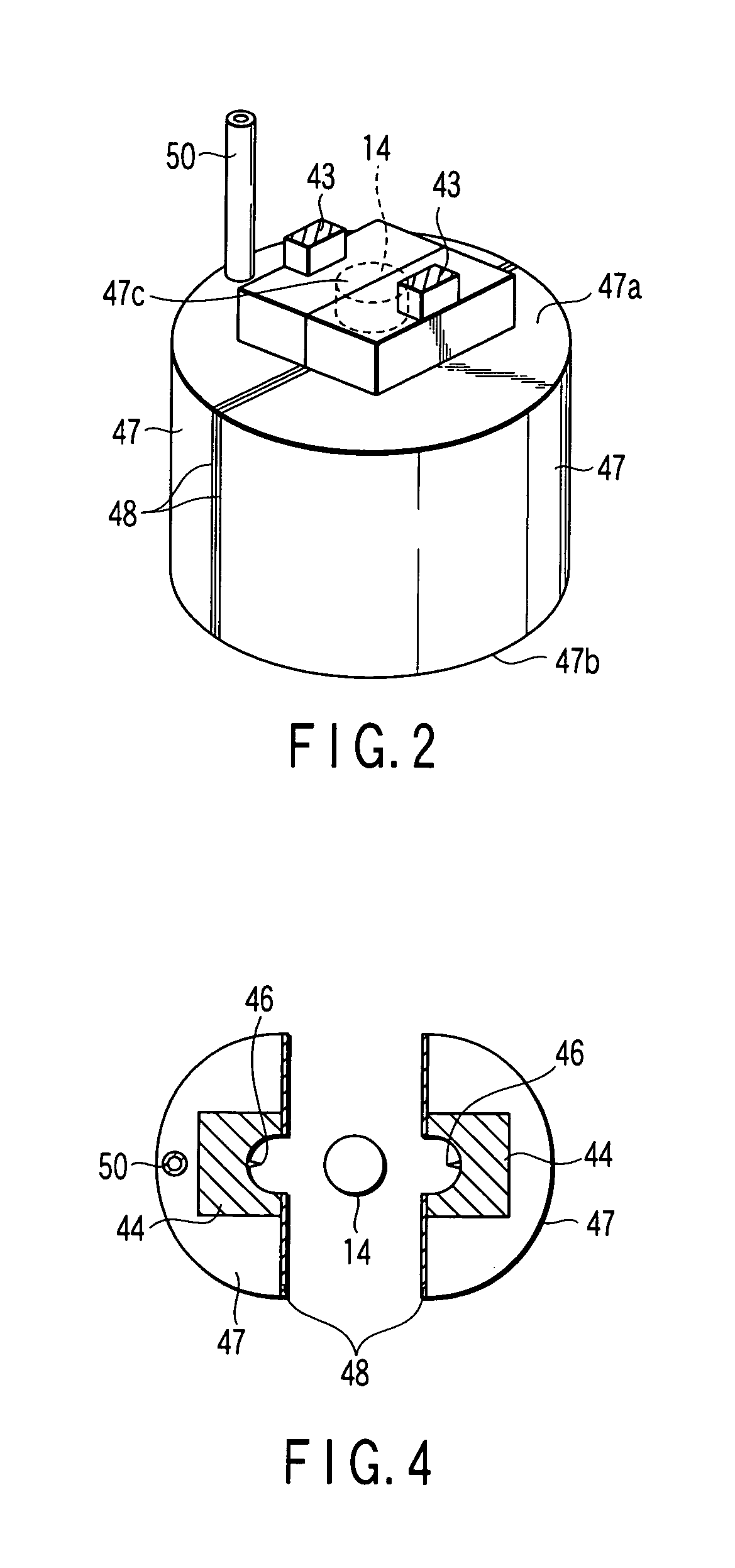
[0019]FIG. 1 is a front view of a cap removal apparatus of a vacuum blood collection tube, FIG. 2 is a perspective view of cover members, FIGS. 3A and 3B are enlarged longitudinal sectional front views showing principal parts, and FIG. 4 is a sectional view taken along line A-A of FIG. 3. Number 11 denotes the vacuum blood collection tube, of which a plastic or glass tubular body 12 contains collected blood 13 therein. An opening of the tubular body 12 is closed by a cap 14 of rubber or synthetic resin so that the tubular body is kept under vacuum inside.

[0020]The vacuum blood collection tube 11 is inserted and held upright in a blood collection tube holder 15. The tube holder 15 is provided with a pair of flanges 17, upper and lower, at the lower end portion of a bottomed cylinder 16 so that an annular groove 18 is defined between the flanges 17. The tube holder 15 is conf...


PUM

PropertyMeasurementUnit
Pressureaaaaaaaaaa
Internal pressureaaaaaaaaaa

Abstract

A cap removal apparatus for a vacuum blood collection tube is configured to remove a cap from the collection tube of which an opening is closed by the cap so that the tube is kept under vacuum inside. The cap removal apparatus comprises, a tube clamping mechanism which clamps the collection tube upright in a cap removal position, a chuck mechanism which is disposed in the cap removal position and chucks the cap of the collection tube, seal pressure reduction unit which is disposed in the a chuck mechanism and configured to seal a region around the opening including the cap and reduce the pressure of the sealed region to substantially the same level as the internal pressure of the collection tube when the cap is chucked, and a lift mechanism which raises the chuck mechanism from a cap chucking position, thereby removing the cap from the collection tube.

Description

CROSS-REFERENCE TO RELATED APPLICATIONS[0001]This application is based upon and claims the benefit of priority from prior Japanese Patent Application No. 2007-127086, filed May 11, 2007, the entire contents of which are incorporated herein by reference.BACKGROUND OF THE INVENTION[0002]1. Field of the Invention[0003]The present invention relates to a cap removal apparatus and a cap removal method for vacuum blood collection tubes, configured to automatically remove caps from vacuum blood collection tubes that contain collected blood.[0004]2. Description of the Related Art[0005]A test tube that contains blood has its opening closed by a cap, such as a rubber cap. In a blood aliquoting / dispensing apparatus, for example, a large number of test tubes are supported one after another by test tube holders or the like and conveyed by a conveyor belt. When the test tube reaches a cap removal position in the course of conveyance, the conveyance of the test tube is temporarily stopped, and the ...

Claims


Application Information

Patent Timeline
IPC IPC(8): B67B7/20B23P19/04A61B5/15A61B5/154A61J1/14B01L99/00
CPCY10T29/49822B67B7/20A61B5/154A61J1/14
Inventor ITOH, TERUAKI
Owner IDS CO LTD
Why Eureka
Eureka Blog
Learn More