
Gas reformulation system comprising means to optimize the effectiveness of gas conversion

a gas reformulation system and gas conversion technology, applied in the field of gas reformulation, can solve the problems of system optimization of energy mechanisms and overall effectiveness, designed to reformulate gas, etc., to achieve the effect of minimizing the amount of energy required, maximizing the percentage of gas reformulated, and speeding up the speed, efficiency and thoroughness of reformulation reactions

Inactive Publication Date: 2008-11-13
PLASCO ENERGY GROUP INC
View PDF101 Cites 69 Cited by
  • Summary
  • Abstract
  • Description
  • Claims
  • Application Information

AI Technical Summary

Benefits of technology

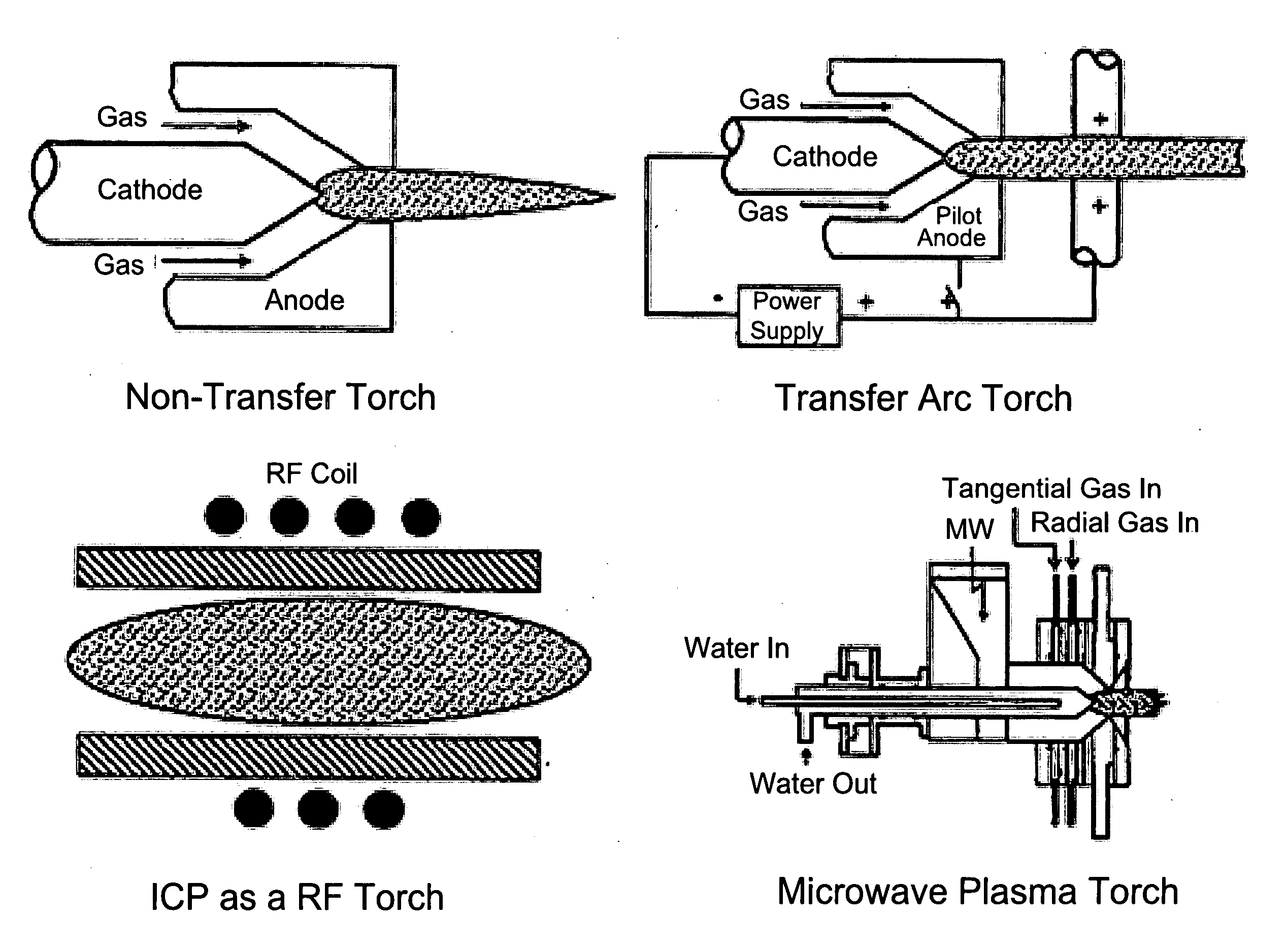
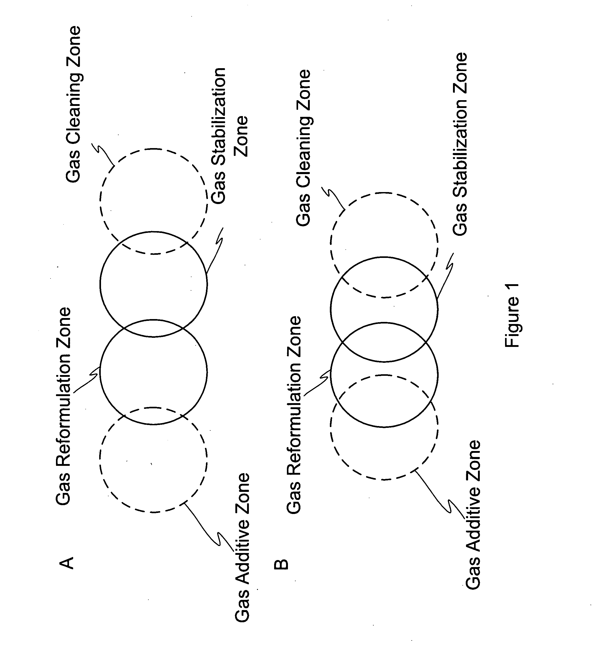
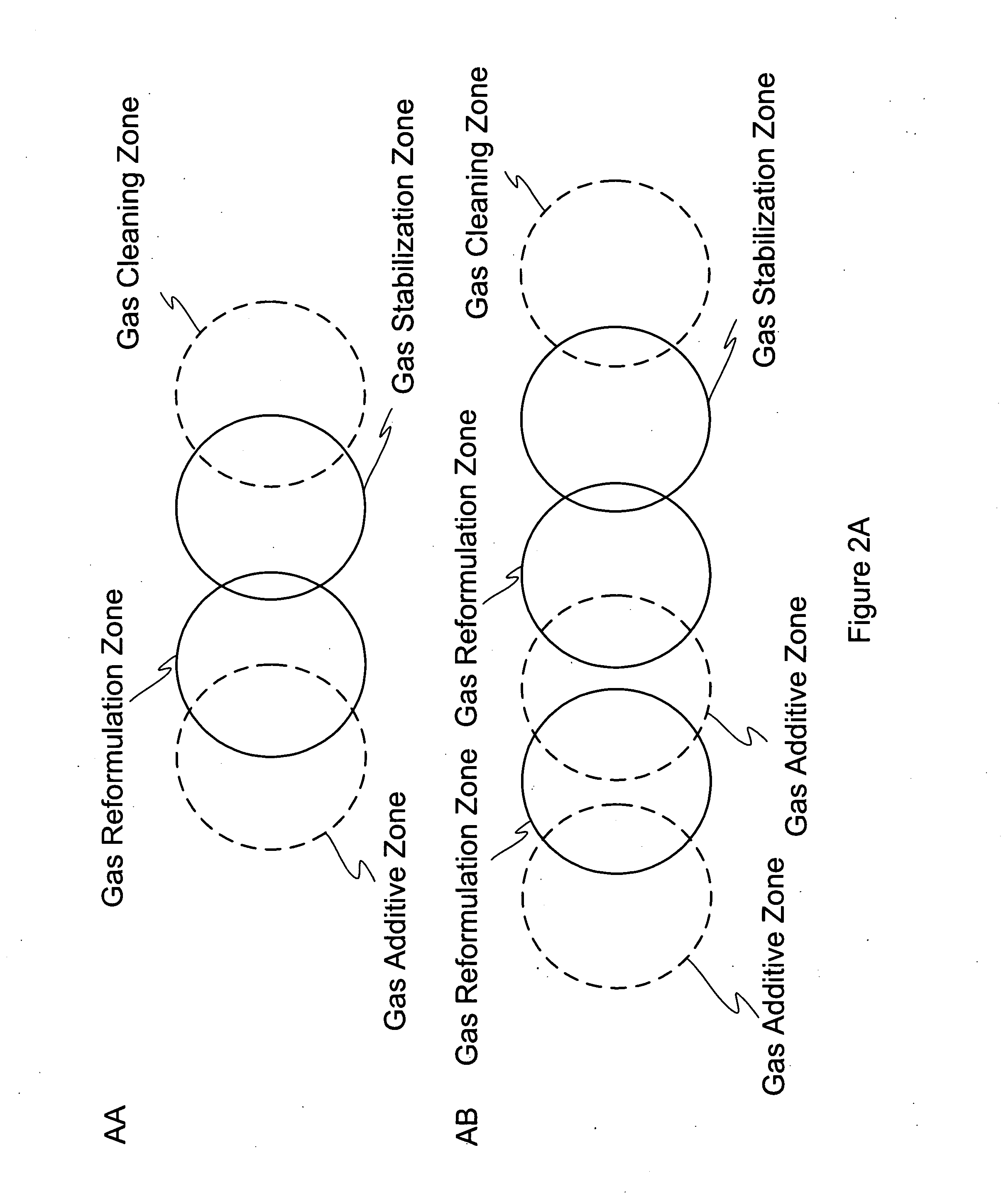
[0020]In accordance with another aspect of the invention, there is provided a process for reformulating an initial gas into a reformulated gas having desired characteristics, comprising one or more of the following steps sensing at least one characteristic of the initial gas; modifying process inputs for reformulation based on the sensed characteristics of the initial gas, and on the desired characteristics of the output gas; applying a gas energizing field sufficient to reformulate the majority of the gaseous molecules into their constituents; promoting efficient process acceleration for the reformulation of the constituents into a reformulated gas of designed characteristics; promoting the de-energization and stabilization of the newly formed molecules to maintain the designed characteristics; and managing the efficient conversion of the initial gas to the output gas.
[0025]In particular, this system has been designed to optimize the transfer of energy from one or more sources to gas of an initial chemical composition (preformulated gas) and throughout the reformulation process such that the gas reformulates into gas of a designed chemical composition in an effective manner. This system comprises design strategies embodied within the Gas Manipulators that function to facilitate the speed, efficiency and thoroughness of the reformulation reactions as the gas passes through the gas reformulation chamber, to minimize the amount of energy required overall to reformulate gas, and to maximize the percentage of gas reformulated into gas of a designed chemical composition.

Problems solved by technology

Although this cyclonic oxider, can treat (i.e., clean) the off-gas by oxidizing the contaminates, it is not designed to reformulate the gas into a product gas of designed chemical composition.
The aforementioned systems do not optimize the energetic mechanisms and the overall effectiveness of reformulating the majority of raw syngas to gas of a designed chemical composition.

Method used


Image

  • Gas reformulation system comprising means to optimize the effectiveness of gas conversion
  • Gas reformulation system comprising means to optimize the effectiveness of gas conversion
  • Gas reformulation system comprising means to optimize the effectiveness of gas conversion

Examples


example 1

[0340]This example shows an example of a gas manipulator designed to be retrofitted to an existing gas reformulating chamber design. FIG. 60A shows the gas reformulating system (GRS) 3200 designed to be directly linked to a horizontally oriented, refractory-lined gasifier.

[0341]The gas exits through the gas outlet of the gasifier into the GRS 3200 which is sealably coupled to the gasifier via a mounting flange 3214 which directly connects the gasifier gas outlet with the single conically shaped input gas inlet of the GRS. Air is injected into the input gas stream through swirl ports 3212 to create a swirling motion or turbulence in the input gas stream thereby mixing the input gas and creating a re-circulating vortex pattern within the GRS. The residence time of the gas within the GRS is about 1.2 seconds.

[0342]Referring to FIG. 60A, the GRS comprises a substantially vertically mounted refractory-lined cylindrical chamber having a length-to-diameter ratio of about 3:1 and a single c...


PUM

PropertyMeasurementUnit
temperatureaaaaaaaaaa
temperaturesaaaaaaaaaa

Abstract

This invention provides a system and method for efficient reformulation of an initial gas with associated characteristics into an output gas with desired characteristic parameters, within a substantially sealed, contained, and controlled environment. The gas reformulating system uses a gas energizing field to disassociate the initial gas molecules and molecules of injected process additives of appropriate types and amounts, into their constituents that then recombine to form the output gas with the desired parameters. The gas reformulating system further comprises a control system that regulates the process and thereby enables the process to be optimized. The gas energizing field may be provided at least partly by hydrogen burners or plasma torches.

Description

CROSS-REFERENCE TO RELATED APPLICATIONS[0001]This application claims benefit of priority under 35 U.S.C. § 119(e) from U.S. Provisional Application Ser. No. 60 / 917,410, filed May 11, 2007. This application also claims benefit of priority under 35 U.S.C. § 119(e) from U.S. Provisional Application Ser. No. 60 / 986,213, filed Nov. 7, 2007. This application also claims benefit of priority under 35 U.S.C. §119(e) from U.S. Provisional Application Ser. No. 60 / 986,212, filed Nov. 7, 2007. This application also claims the benefit of priority to International Patent Application No. PCT / CA08 / 00355, filed Feb. 27, 2008. This application also claims benefit of priority under 35 U.S.C. §119(e) from U.S. Provisional Application Ser. No. 61 / 042,571, filed Apr. 4, 2008. The contents of all of the aforementioned applications are hereby expressly incorporated by reference in their entirety and for all purposes.FIELD OF THE INVENTION[0002]This invention pertains to the field of gas reformulation. In pa...

Claims


Application Information

Patent Timeline
Patent Type & Authority Applications(United States)
IPC IPC(8): C07C1/00G01N27/26
CPCC01B2203/0822C10K3/023C01B2203/0861C01B2203/0883C01B2203/142C01B2203/16C01B2203/1619C01B2203/1623C01B2203/1633C01B2203/1671C01B2203/169C01B2203/84C10J3/24C10J3/80C10J2300/1238C10J2300/1861C10J2300/1876C10J2300/1884C01B3/342C01B3/386C01B2203/0827Y02P20/10
Inventor TSANGARIS, ANDREASBACON, MARC
Owner PLASCO ENERGY GROUP INC
Learn More