Apparatus for Manufacturing Molten Irons
Active Publication Date: 2008-11-13
POSCO HLDG INC +1
View PDF2 Cites 15 Cited by
- Summary
- Abstract
- Description
- Claims
- Application Information
AI Technical Summary
Benefits of technology
[0028]In an apparatus for manufacturing molten irons according to the present invention, loss of fine iron ore may be prevented by suppressing adhesion of the fine iron ore in a cyclone of a fluidized-bed reduction reactor in the fluidizing reduction process using fine iron ore.
[0029]In addition, an operating rate of the fluidized-bed reduction reactor may be improved since formation of the adhesive materials can be prevented and time for removing them is not consumed.
Problems solved by technology
As described above, if the flow is interrupted in the cyclone, a large loss of fine iron ore occurs, since the fine iron ore cannot be recovered
Moreover, since considerable working hours are necessary to remove the adhesive materials formed in the cyclone, the blockage phenomenon of the cyclone due to the adhesive materials largely reduces an operating ratio of the fluidized-bed reduction reactor.
Method used
View moreImage
Smart ImageViewing Examples
Examples
experimental example 1
[0076]The collapsing angle of the fine iron ore that contacted a mixed gas containing a reducing gas and a gas containing methane at 50% for a predetermined time was measured.
experimental example 2
[0077]The collapsing angle of the fine iron ore that contacted a mixed gas containing a stat gas containing methane 100% for a predetermined time was measured.
Login to View More PUM
| Property | Measurement | Unit |
|---|---|---|
| Velocity | aaaaa | aaaaa |
| Velocity | aaaaa | aaaaa |
| Shape | aaaaa | aaaaa |
Abstract
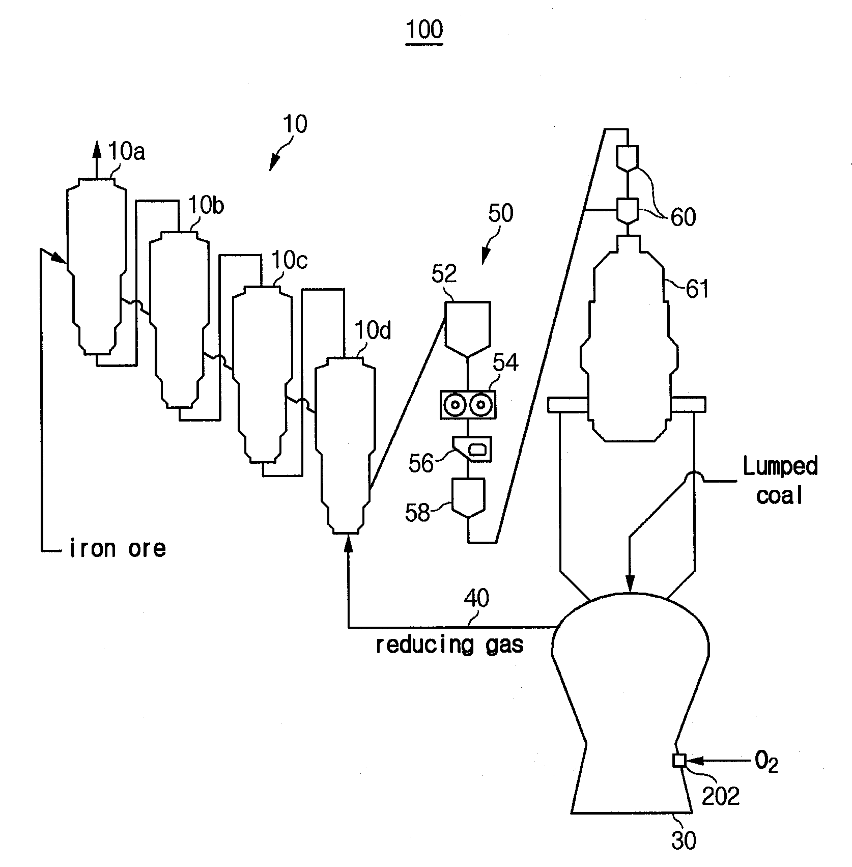
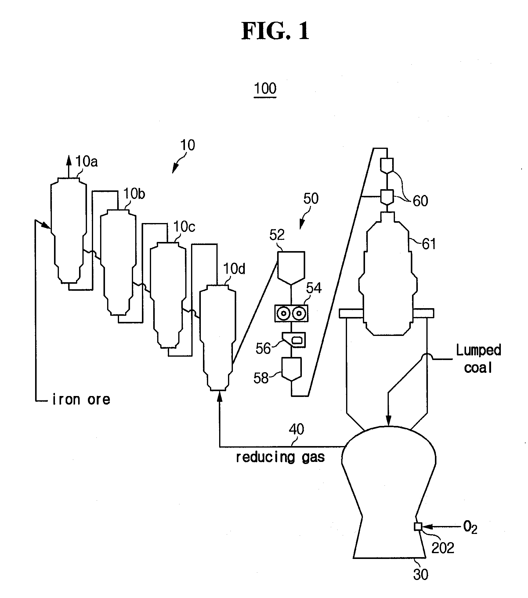
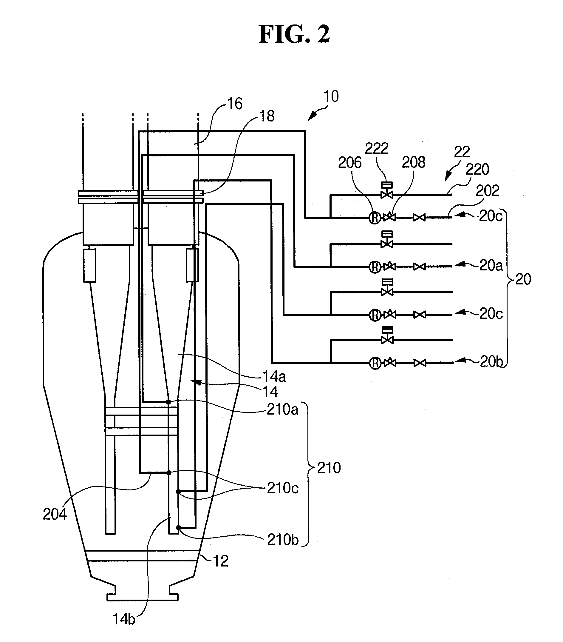
An apparatus for manufacturing molten iron includes i) at least one fluidized-bed reduction reactor that reduces and plasticizes iron ore and converts the iron ore into reduced materials, ii) a melter-gasifier into which the reduced ore is charged and oxygen is injected, the melter-gasifier manufacturing molten iron, and iii) a reducing gas supply line that supplies a reducing gas discharged from the melter-gasifier to the fluidized-bed reduction reactor. The fluidized-bed reduction reactor includes a cyclone that is installed in the fluidized-bed reduction reactor to collect fine iron ore. A gas injector, which prevents the fine ore from adhering by injecting gas containing carbon, is connected to the cyclone.
Description
TECHNICAL FIELD[0001]The present invention relates an apparatus for manufacturing molten irons that prevent fine iron ore from adhering to itself within a cyclone in the fluidized-bed reactor in a smelting reduction process using fine ore.BACKGROUND ART[0002]The iron and steel industry is a core industry that supplies the basic materials needed in construction and in the manufacture of automobiles, ships, home appliances, and many of the other products we use. It is also an industry with one of the longest histories that has progressed together with humanity. In an iron foundry, which plays a pivotal roll in the iron and steel industry, after molten iron, which is pig iron in a molten state, is produced by using iron ore and coal as raw materials, steel is produced from the molten iron and then supplied to customers.[0003]At present, approximately 60% of the world's iron production is realized by using the blast furnace process developed from the 14th century. In the blast furnace p...
Claims
Login to View More Application Information
Patent Timeline
 IPC IPC(8): C22B1/10C21B13/00C21B13/14F27B15/02F27B15/10F27D25/00
CPCB01J8/0055B01J8/1818B01J8/1827B01J8/24B01J8/26B01J8/28B01J8/44B01J2208/00017B01J2208/00557B01J2208/00681B01J2219/0004C21B13/002C21B13/0033C21B13/0073C21B13/143F27B15/10C21B2100/44C21B13/00C21B11/00
Inventor SHIN, MYOUNG-KYUNKIM, SANG-HYUNLEE, JUN-HYUKNAM, KUNG-WON
Owner POSCO HLDG INC
Features
- R&D
- Intellectual Property
- Life Sciences
- Materials
- Tech Scout
- Unparalleled Data Quality
- Higher Quality Content
- 60% Fewer Hallucinations
Learn More Browse by: Latest US Patents, China's latest patents, Technical Efficacy Thesaurus, Application Domain, Technology Topic, Popular Technical Reports.
© 2025 PatSnap. All rights reserved.Legal|Privacy policy|Modern Slavery Act Transparency Statement|Sitemap|About US| Contact US: help@patsnap.com


