

Magnetic Force Rotation Device
a magnetic force and rotation device technology, applied in the direction of magnetic circuit rotating parts, dynamo-electric machines, magnetic circuit shape/form/construction, etc., can solve problems such as unsatisfactory transformer interference effect, and achieve the effects of lowering torque pulsation, high efficiency, and high outpu
- Summary
- Abstract
- Description
- Claims
- Application Information
AI Technical Summary
Benefits of technology
Problems solved by technology
Method used
Image

Examples
first embodiment
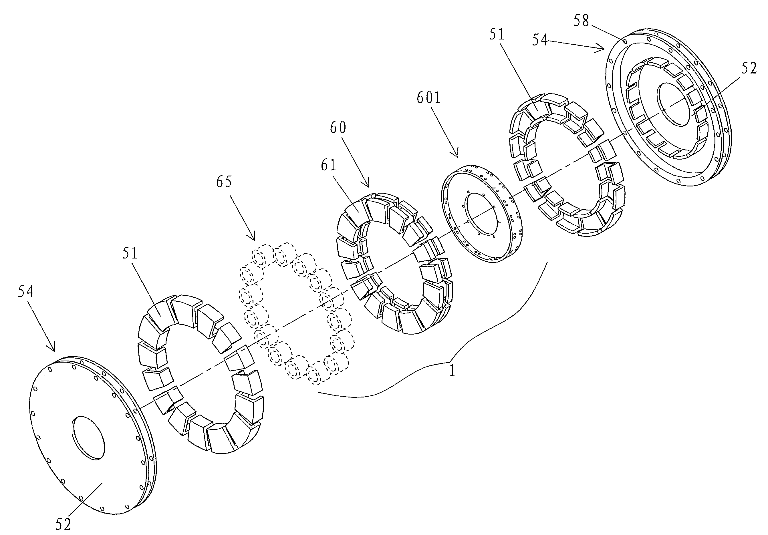
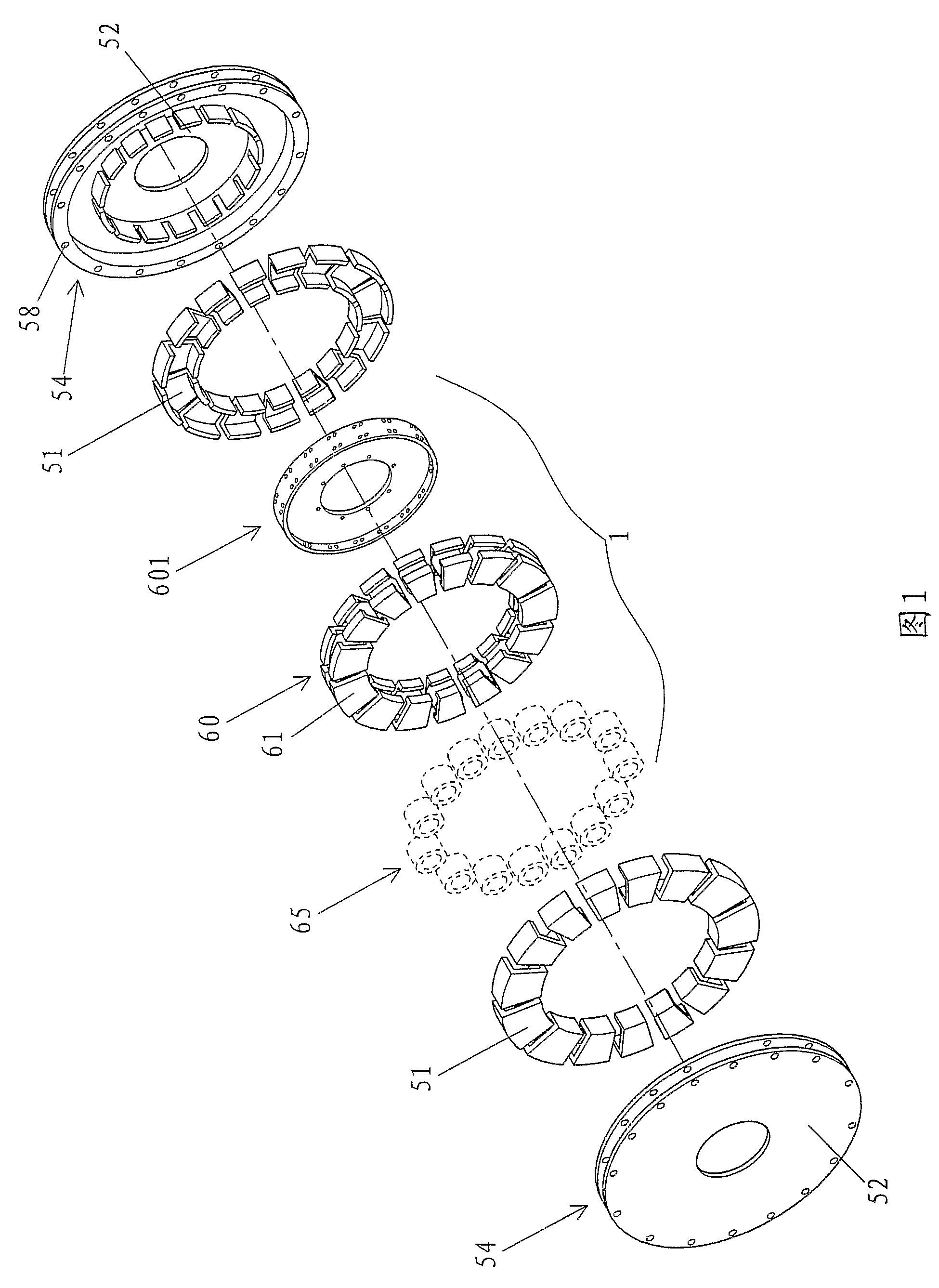
[0032]FIG. 1 is an exploded perspective view illustrating members of a magnetic force rotation device in accordance with the present invention. The magnetic force rotation device includes a stator and a rotor. A plurality of electromagnetic members 60 are arranged along a circumferential direction about a revolving shaft to form a stator wheel-shaped ring after assembling the components included in the bracket. Each electromagnetic member of the stator wheel-shaped ring includes twin poles connected by a ferromagnetic core segment on which a winding 65 is formed. Each of the twin poles 61 of the electromagnetic member is substantially U-shaped in cross section, wherein a bottom one of three pole faces on the outer side of the U-shaped cross section is generally perpendicular to the revolving shaft whereas the remaining two pole faces of the U-shaped cross section face respective radial component air-gaps. A stator support ring 601 made of non-ferromagnetic material serves as a fixin...
third embodiment
[0040]FIG. 8 is a cross section illustrating a portion of the magnetic force rotation device in accordance with the present invention, with a portion of the stator of the magnetic force rotation device after assembly being shown in FIG. 7. The frame of FIG. 8 improves the spatial distribution of the flux while providing a large air-gap surface area. Each substantially U-shaped pole 61 of FIG. 4 is replaced by a substantially U-shaped pole 61B that is more symmetric, in which the fixing pattern of the electromagnetic members of the stator is modified to obtain a more symmetric structure. Besides allowing coupling of two adjoining balancing / fixing plates, the holes of the balancing / fixing plates 612 can be coupled with the holes of the stator support rod 603. To match the change of the electromagnetic members of the stator, each U-shaped permanent magnet 51 of the rotor of FIG. 4 is replaced by a U-shaped permanent magnet 51B with a larger air-gap surface area. Compared to the U-shape...
PUM
 Abstract
Description
Claims
Application Information