Constant-Voltage Power Supply Circuit with Fold-Back-Type Overcurrent Protection Circuit

a protection circuit technology, applied in the direction of electric variable regulation, process and machine control, instruments, etc., can solve the problems of increasing the current consumption of the constant-voltage power supply circuit, increasing the cost, increasing the chip size,

Inactive Publication Date: 2008-11-13
RICOH ELECTRONIC DEVICES CO LTD
View PDF8 Cites 24 Cited by
  • Summary
  • Abstract
  • Description
  • Claims
  • Application Information

AI Technical Summary

Benefits of technology

[0015]It is another and more specific object of the present invention to provide a constant-voltage power supply circuit having an overcurrent protection circuit and a method of controlling such a constant-voltage power supply circuit in which the short-circuit current can be lowered to a predetermined current amount without increasing the circuit size of the overcurrent protection circuit and without increasing the operating current of the overcurrent protection circuit.
[0018]According to at least one embodiment of the present invention, as the overcurrent protection circuit unit having a fold-back characteristic starts an operation, the bias current adjusting circuit unit suspends the supply of the bias current to the circuit for driving the output transistor, such as the error amplifying circuit unit, which is provided in the constant-voltage power supply circuit. This serves to leave behind only a fixed bias current. Accordingly, even when the a transistor having a drive power compatible to or smaller than that of a conventional overcurrent protection circuit is used, and the operation of the output transistor is controlled upon the operation of the overcurrent protection circuit, the short-circuit current set by the overcurrent protection circuit can be fully reduced to a desired current amount.

Problems solved by technology

In the method of increasing the bias current to the error amplifying circuit, only a limited increase in the bias current can be made since such an increase results in the current consumption of the constant-voltage power supply circuit being increased.
The drive power of the output node of the operational amplifier A101 is thus extremely large, so that the drive power of the PMOS transistor M104 used in the overcurrent protection circuit 105 is not sufficient to bring the short-circuit current corresponding to the short-circuiting of the output voltage Vout to the point A shown in FIG. 8, resulting in the actual characteristics being those as shown by the solid line, which can bring the short-circuit current only to a point B. As a result, the power loss at the output transistor M101 becomes significant to generate excess heat, which may cause a failure to the IC when the constant-voltage power supply circuit is implemented as an IC chip.
An increase in the drive power of the PMOS transistor M104 requires an increase in the device size of the PMOS transistor M104, which results in the cost being increased due to an increase in the chip size when the constant-voltage power supply circuit 100 is implemented as an IC chip.
Further, there is a need to increase the operating current of the overcurrent protection circuit 105, resulting in an increase in power consumption.

Method used


Image

  • Constant-Voltage Power Supply Circuit with Fold-Back-Type Overcurrent Protection Circuit
  • Constant-Voltage Power Supply Circuit with Fold-Back-Type Overcurrent Protection Circuit
  • Constant-Voltage Power Supply Circuit with Fold-Back-Type Overcurrent Protection Circuit

Examples


first embodiment

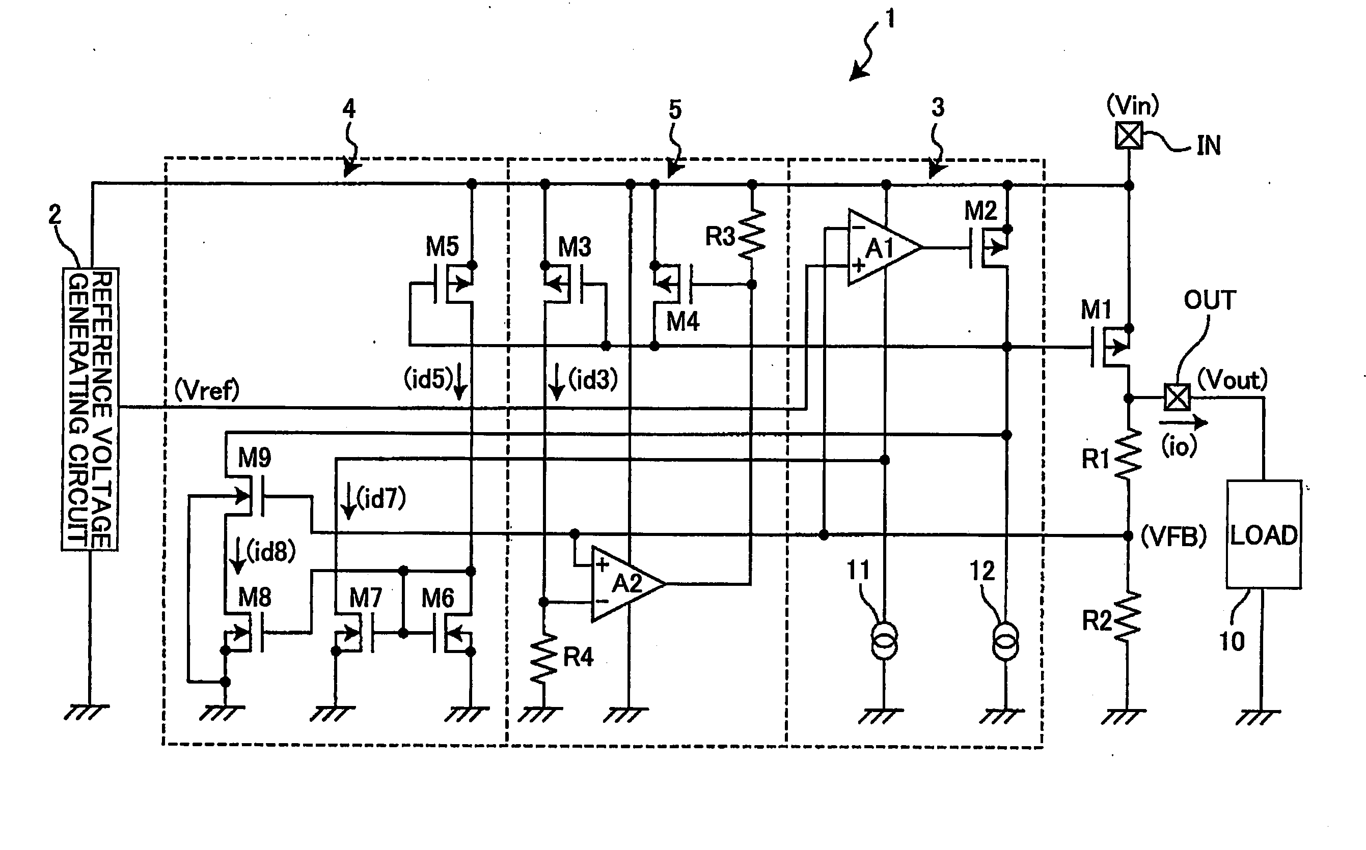
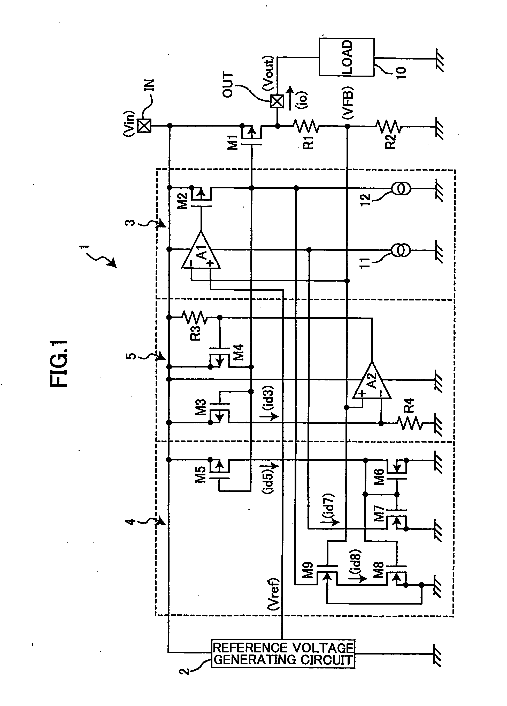
[0028]FIG. 1 is a drawing showing an example of a constant-voltage power supply circuit according to a first embodiment of the present invention.

[0029]In FIG. 1, a constant-voltage power supply circuit 1 generates a predetermined constant voltage from an input voltage Vin input into an input terminal IN to output an output voltage Vout from an output terminal OUT. The output voltage Vout output from the output terminal OUT is supplied to a load 10 coupled to the output terminal OUT. The constant-voltage power supply circuit 1 may be implemented as a single IC chip.

[0030]A constant-voltage power supply circuit 1 of FIG. 1 includes a reference voltage generating circuit 2 for generating and outputting a predetermined reference voltage Vref, output-voltage-detection-purpose resistors R1 and R2 for generating and outputting a divided voltage VFB by dividing the output voltage Vout, an output transistor M1 comprised of a PMOS transistor for controlling a current io produced at the output...

second embodiment

[0048]In the first embodiment described above, a single error amplifying circuit is provided to control the operation of the output transistor. Alternatively, the present invention may be applicable to a constant-voltage power supply circuit having such configuration that the operation of the output transistor is controlled simultaneously by a first error amplifying circuit having a superior direct-current characteristic with as large a direct-current gain as possible and by a second error amplifying circuit responding at high speed to the fluctuation of the output voltage Vout. The second embodiment of the present invention is directed to such a configuration.

[0049]FIG. 4 is a drawing showing an example of a constant-voltage power supply circuit according to a second embodiment of the present invention. In FIG. 4, the same elements as those of FIG. 1 are referred to by the same numerals, and a description thereof will be omitted. Differences from the configuration of FIG. 1 will on...

third embodiment

[0058]In the first and second embodiments described above, a phase compensation circuit may be provided to perform a phase compensation that lowers the gain of the bias current adjusting circuit with respect to the frequency band of signals generated on the negative feedback loop. The third embodiment of the present invention is directed to such a configuration.

[0059]FIG. 5 is a drawing showing an example of a constant-voltage power supply circuit according to a third embodiment of the present invention. FIG. 5 shows as an example a constant-voltage power supply circuit having the same configuration as that shown in FIG. 4. The same elements as those of FIG. 4 are referred to by the same numerals, and a description thereof will be omitted. Differences from the configuration of FIG. 4 will only be described.

[0060]FIG. 5 differs from FIG. 4 in that a phase compensation circuit is additionally provided in the bias current adjusting circuit 4 of FIG. 4 to perform a phase compensation th...


PUM


Abstract

A constant-voltage power supply circuit for converting an input voltage applied to an input terminal into a predetermined constant voltage for output from an output terminal includes an output transistor to supply from the input terminal to the output terminal an output current responsive to an applied control signal, an error amplifying circuit unit to receive a predetermined bias current to control an operation of the output transistor, and a bias current adjusting circuit unit to supply the error amplifying circuit unit with the bias current responsive to the output current output from the output transistor, wherein the bias current adjusting circuit unit is configured to suspend the supply of the bias current to the error amplifying circuit unit in response to lowering of the output voltage to a predetermined voltage.

Description

TECHNICAL FIELD[0001]The present invention generally relates to constant-voltage power supply circuits provided with an overcurrent protection circuit having a fold-back current limiting characteristic and methods of controlling such constant-voltage power supply circuits, and particularly relates to a constant-voltage power supply circuit and a method of controlling a constant-voltage power supply circuit in which provision is made to increase bias currents for various circuits constituting the constant-voltage power supply circuit in response to an increase in the output current, thereby enabling the overcurrent protection circuit to operate reliably.BACKGROUND ART[0002]In order to improve the response speed of a constant-voltage power supply circuit in response to the fluctuation of its output voltage, there is a known method of increasing a bias current supplied to a circuitry such as an error amplifying circuit constituting the constant-voltage power supply circuit. Another kno...

Claims


Application Information

Patent Timeline
Patent Type & Authority Applications(United States)
IPC IPC(8): G05F1/569
CPCG05F1/56
Inventor NAGATA, TOSHIHISA
Owner RICOH ELECTRONIC DEVICES CO LTD
Why Eureka
Try Eureka