Optical Device With Vibration Compensation

a technology of optical components and compensation, applied in the field of optical devices, can solve the problems of not being able to achieve the stabilization in the z direction (parallel to the optical axis), needing a separate component for vibration damping, and relatively large and heavy (linear) motors for adjustment and counter-control of optical components

Inactive Publication Date: 2008-11-13
LEICA INSTR SINGAPORE PTE
View PDF6 Cites 15 Cited by
  • Summary
  • Abstract
  • Description
  • Claims
  • Application Information

AI Technical Summary

Benefits of technology

[0014]Because the deformations of the mirror surfaces can be accomplished electronically, a virtually inertia-free vibration compensation in all three spatial directions in real time is therefore possible.
[0015]It is particularly advantageous if the deformable mirror surface provided on the at least one deflection element is embodied as a micromirror array that comprises an arrangement of individually controllable micromirrors whose spatial orientation is adjustable. Such micromirror arrays are known per se from the prior art and will therefore not be further explained hereinafter. The principal advantage of a micromirror array is that only the micromirrors, movably mounted on a base frame, need to be tilted in order to modify the deflection of a beam path, without moving the base frame itself. The individual micromirrors can be controlled electronically. The micromirrors are advantageously arranged on a two-dimensional matrix. Each micromirror may advantageously be tilt or pivoted about two mutually perpendicular tilt axes. In order to compensate for vibration-related displacements in the X and / or Y direction, the individual micromirrors can be correspondingly pivoted about the first and / or second tilt axis. To compensate for vibration-related Z displacements, the micromirrors are to be arranged as a whole, for example, spherically, in order (as already stated) to modify the effective focal length of the principal objective.

Problems solved by technology

A disadvantage of this mechanical stabilization or decoupling of the microscope is the need for a separate component for vibration damping.
The use of relatively large and heavy (linear) motors for adjustment and counter-control of the optical components requires very accurate control, and cannot achieve stabilization in the Z direction (parallel to the optical axis).
A further disadvantage of the known vibration compensation system is the system-inherent inertia of the vibration dampers that are used; this must be taken into account in the vibration compensation control system and results in a corresponding large outlay for control technology.

Method used


Image

  • Optical Device With Vibration Compensation
  • Optical Device With Vibration Compensation
  • Optical Device With Vibration Compensation

Examples


Embodiment Construction

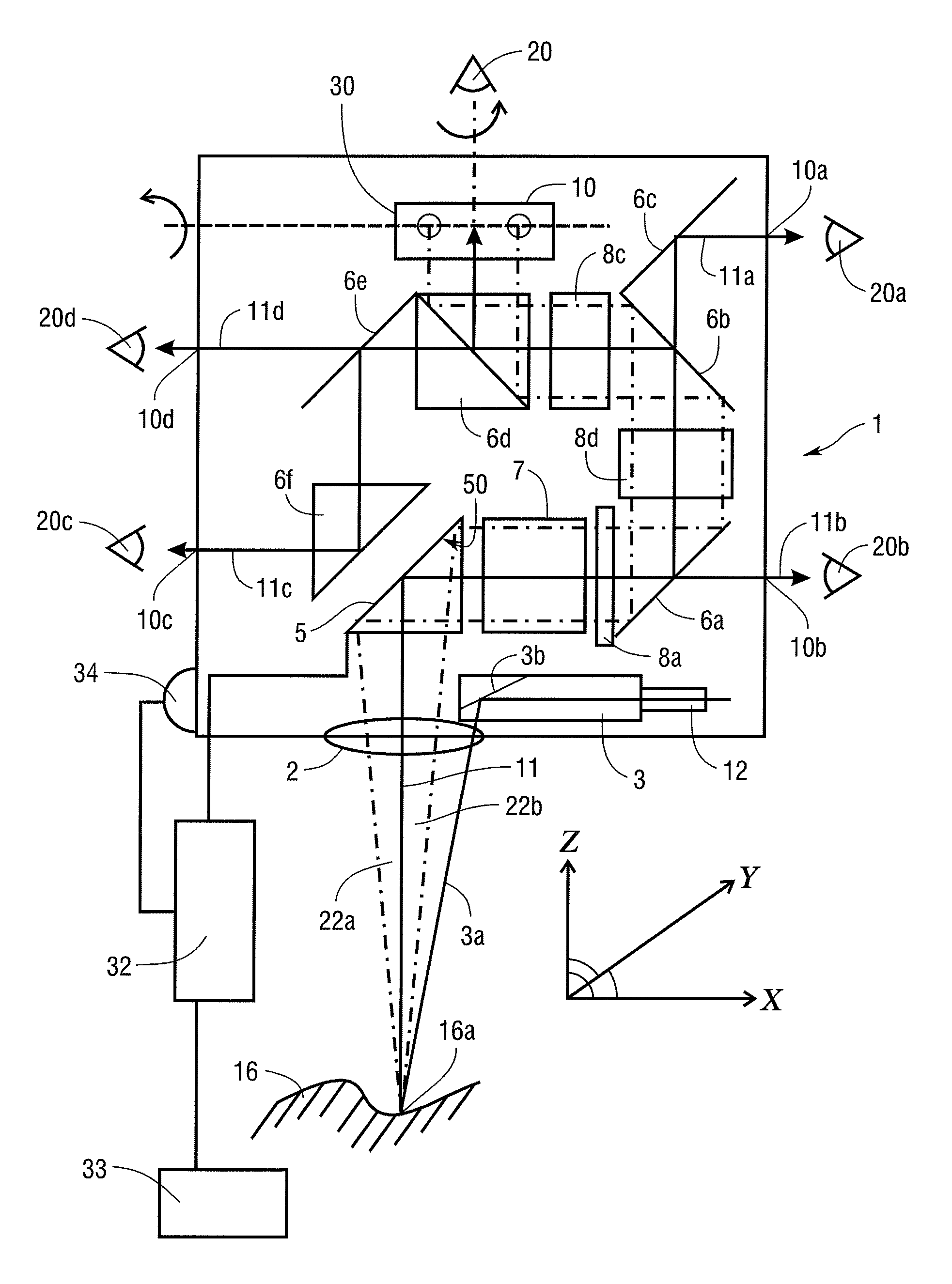
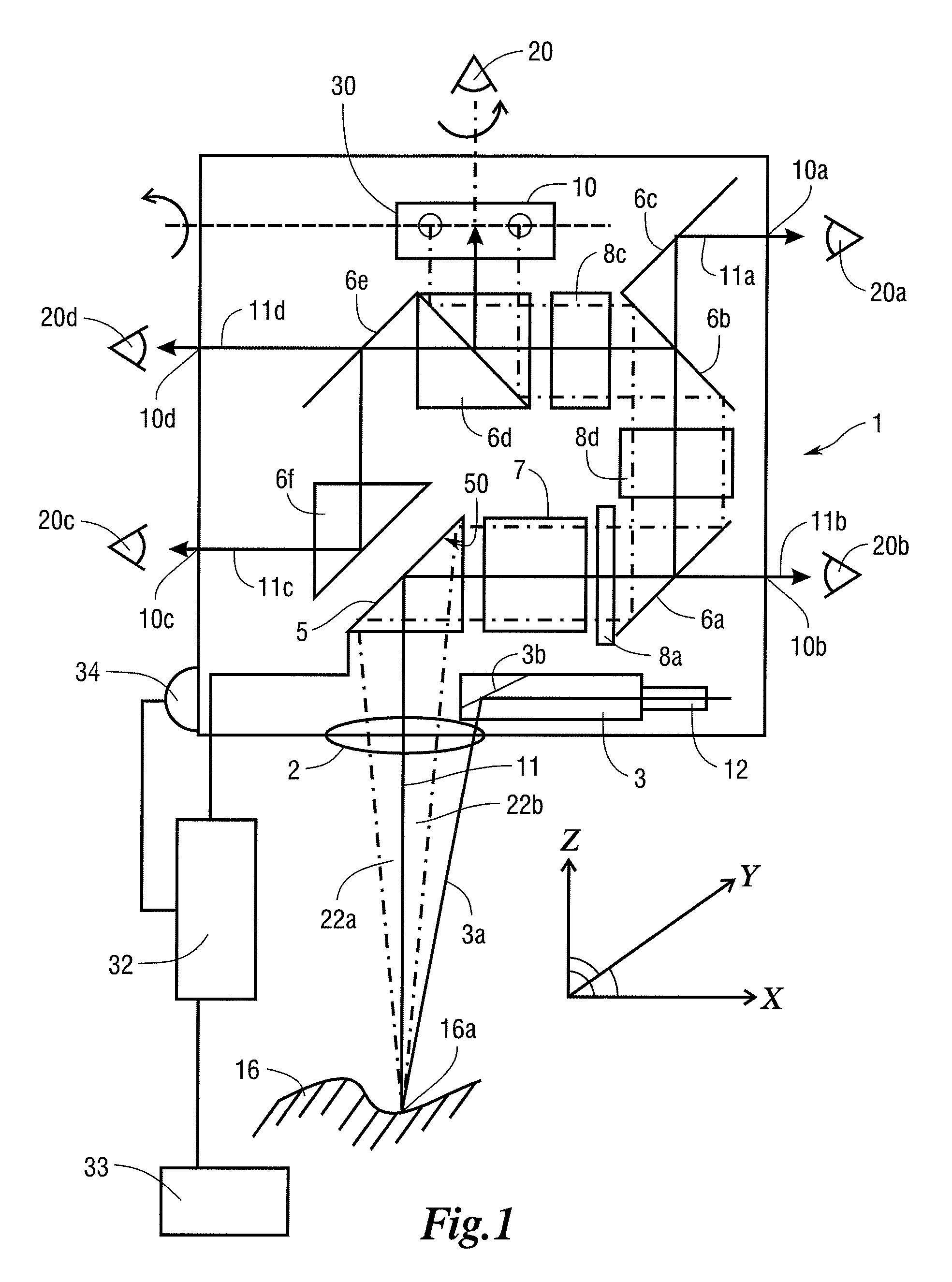
[0023]FIG. 1 schematically shows the configuration of a stereomicroscope 1 having multiple ports 10, 10a, 10b, 10c, and 10d for multiple observers 20, 20a, 20b, 20c, and 20d. The observers can be principal and / or assistant observers. Stereomicroscope 1 is suitable in particular for use as a surgical microscope, in particular in opthalmology. Here, the surgeon usually functions as the principal observer, who is assisted by multiple assistants. Outcoupling of the observation beam path to a documentation device via a corresponding documentation port is, of course, also possible. Port 10 can be configured with a pivotable deflection element 30. Stereomicroscope 1 possesses a principal objective 2 with which a specimen 16 can be observed. Principal objective 2 defines an observation beam path that defines a beam base point 16a on specimen 16 in accordance with the focal length of principal objective 2.

[0024]In the embodiment of stereomicroscope 1 depicted in FIG. 1, zoom system 7 is embo...


PUM


Abstract

The present invention relates to an optical device, in particular a microscope (1), that comprises a beam path in which is arranged at least one deflection element (5, 6a to 6f) for deflecting the beam path, at least one vibration sensor (34) being arranged in or on the optical device; at least one of the deflection elements (5, 6a to 6f) comprising a mirror having a controllably deformable mirror surface (50); and a control unit (32) being provided that, as a function of the output signal of the vibration sensor (34), applies control to the at least one deflection element (5, 6a to 6f) in order to adjust the mirror surface (50) in such a way that vibrations of the optical device are compensated for by a correspondingly opposite-phase adjustment of the mirror surface (50).

Description

CROSS REFERENCE TO RELATED APPLICATIONS[0001]This application claims priority of German patent application 10 2007 021 981.6 filed May 10, 2007, which is incorporated by reference herein.FIELD OF THE INVENTION[0002]The present invention relates to an optical device, in particular a microscope, that comprises a beam path in which is arranged at least one deflection element for deflecting the beam path. The invention relates in particular to a microscope having a principal objective that defines an observation beam path along an optical axis, said observation beam path representing the aforesaid beam path of the optical device. These microscopes can be, in particular, stereomicroscopes and surgical microscopes.BACKGROUND OF THE INVENTION[0003]A generic optical device embodied as a stereomicroscope is known from DE 102 55 960 A1. The stereomicroscope has a principal objective and a zoom system arranged downstream said objective. Since the zoom system is arranged in a “lying” manner or ...

Claims


Application Information

Patent Timeline
Patent Type & Authority Applications(United States)
IPC IPC(8): G02B26/08
CPCG02B21/22G02B26/0833
Inventor SANDER, ULRICH
Owner LEICA INSTR SINGAPORE PTE
Why Eureka
Try Eureka