Increasing Reliability and Reducing Latency in a Wireless Network

a wireless network and reliability technology, applied in the field of wireless communication, can solve the problems of requiring a relatively high overhead, communication networks with specific requirements that are not fully satisfied, and architects and developers often encounter new problems which are not easily addressed, so as to achieve the effect of conserving power

Active Publication Date: 2008-11-13
FIELDCOMM GRP INC
View PDF105 Cites 97 Cited by
  • Summary
  • Abstract
  • Description
  • Claims
  • Application Information

AI Technical Summary

Benefits of technology

[0017]If desired, the dedicated service may dynamically create and destroy superframes in view of changes in network conditions such as data bursts, congestion, block transfers, and network devices entering or leaving the network. Moreover, a network device or the dedicated service may efficiently deactivate a superframe without destroying the superframe by issuing a particular command. If desired, the dedicated service may be a software entity running on a dedicated physical host, or the dedicated service may run on a gateway device connecting the wireless mesh network to an external network or host.
[0019]If desired, the dedicated service may create long superframes for a transient device that periodically wakes up according to a predefined schedule, thereby eliminating the need for the transient device to negotiate resources for each transmission session. In yet another embodiment, the transient device conserves power by transmitting data only according to the necessary update rate of the transient device.

Problems solved by technology

For example, a certain routing technique may provide a high level of reliability in data delivery but may also require a relatively high overhead.
Thus, while there are many known approaches to routing and many protocols compatible with these routing methods, there remain communication networks with the specific requirements that are not fully satisfied by any of the available routing methods and protocols.
Moreover, as new types of communication networks, with the increasing demands for efficiency, throughput, and reliability, emerge in various industrial and commercial applications, the architects and developers frequently encounter new problems which are not easily addressed by the existing protocols and the associated routing techniques.
As one of ordinary skill in the art will recognize, modifying or expanding addressing schemes is a complicated and expensive process.
On the other hand, defining addressing schemes with large capability for small networks creates an unnecessary overhead.
However, the HART protocol currently requires the use of dedicated, hardwired communication lines, resulting in significant wiring needs within a process plant.
However, there are significant hurdles in the process control industry that limit the full scale incorporation, acceptance and use of wireless technology.
In particular, the process control industry requires a completely reliable process control network because loss of signals can result in the loss of control of a plant, leading to catastrophic consequences, including explosions, the release of deadly chemicals or gases, etc.
Moreover, there have been many advances in the use of wireless communication systems in general that may be applicable to the process control industry, but which have not yet been applied to the process control industry in a manner that allows or provides a reliable, and in some instances completely wireless, communication network within a process plant.
Of course, much of the methodology developed to address these concerns on wired networks does not apply to wireless communications because of the shared and open nature of the medium.
Moreover, some wireless networks operate in the part of the spectrum that is unlicensed, or open to the public.
However, current measurement devices usually require power, communications infrastructure, configuration, and support infrastructure which simply is not available.

Method used


Image

  • Increasing Reliability and Reducing Latency in a Wireless Network
  • Increasing Reliability and Reducing Latency in a Wireless Network
  • Increasing Reliability and Reducing Latency in a Wireless Network

Examples


Embodiment Construction

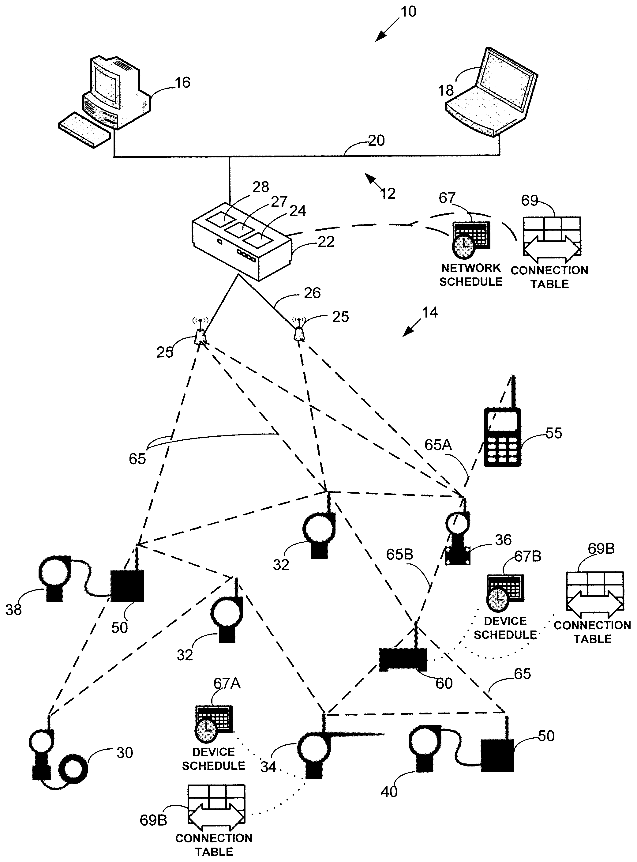
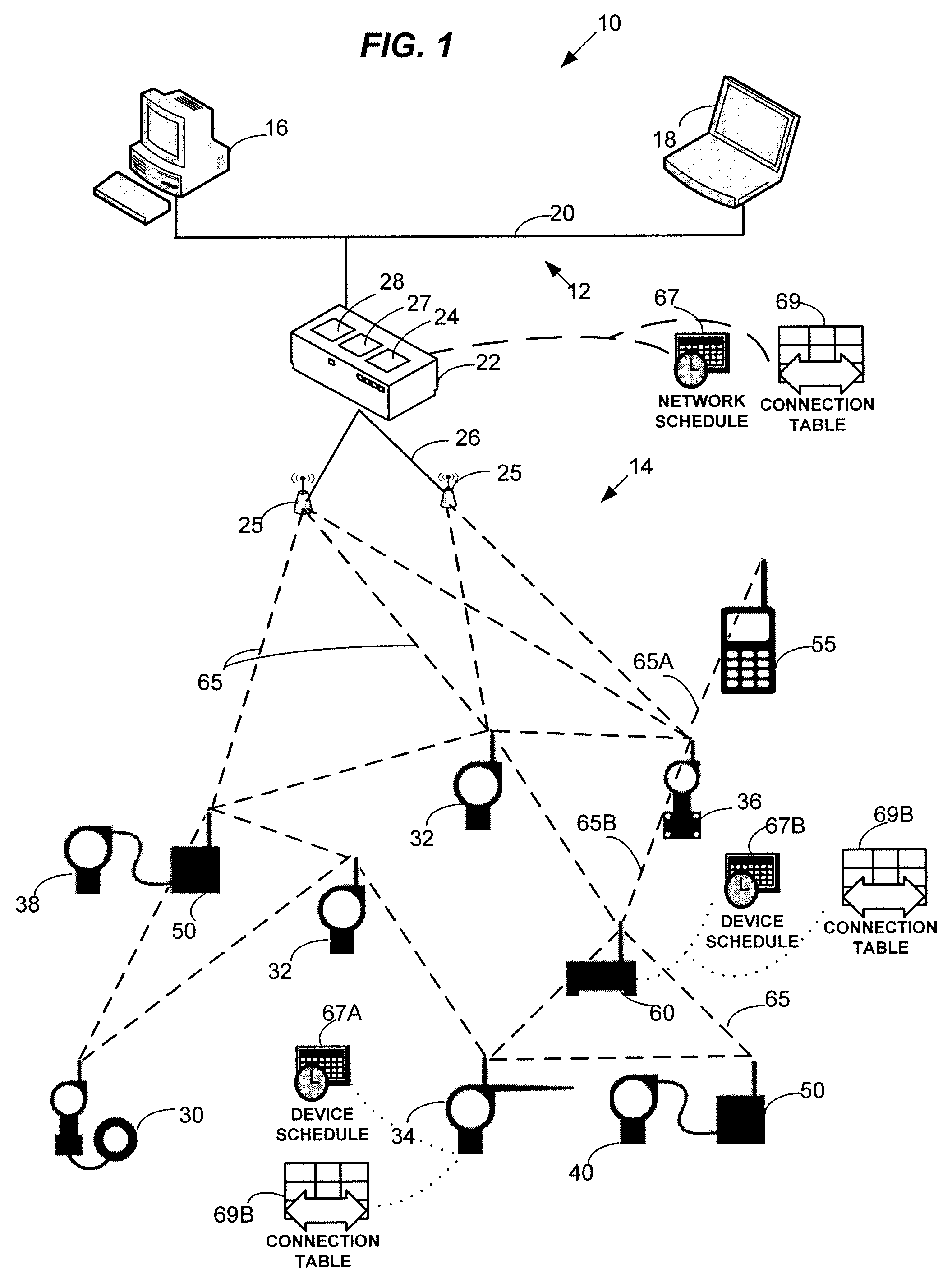
[0038]FIG. 1 illustrates an exemplary network 10 in which the scheduling and routing techniques described herein may be used. In particular, the network 10 may include a plant automation network 12 connected to a wireless communication network 14. The plant automation network 12 may include one or more stationary workstations 16 and one or more portable workstations 18 connected over a communication backbone 20 which may be implemented using Ethernet, RS-485, Profibus DP, or using other suitable communication hardware and protocol. The workstations and other equipment forming the plant automation network 12 may provide various control and supervisory functions to plant personnel, including access to devices in the wireless network 14. The plant automation network 12 and the wireless network 14 may be connected via a gateway device 22. More specifically, the gateway device 22 may be connected to the backbone 20 in a wired manner and may communicate with the plant automation network 1...


PUM


Abstract

A mesh communication network for use in, for example, process control plants includes a plurality of network devices transmitting and receiving data according to a network schedule defined as a set of concurrent overlapping superframes, and along a set of graphs defining communication paths between pairs of network devices. A network manager residing in or outside the communication network develops a routing scheme for the network by analyzing the topology of the network and defining a set of graphs for use in routing or transmitting data between various nodes of the network, each graph including one or more communication paths between pairs of network devices. Concurrently or consequently, the network manager defines the network schedule in view of at least transmission requirements, power availability, and signal quality at each network device. If desired, the network manager may begin to define the network schedule upon completing the definition of the graphs of the communication network, so that the network manager may define the network schedule in view both the defined graphs and the transmission, power, etc. parameters associated with each network device.

Description

CROSS-REFERENCE TO RELATED APPLICATIONS[0001]This application is based on and claims the benefit of priority to U.S. Provisional Application No. 60 / 911,795, entitled “Routing, Scheduling, Reliable and Secure Operations in a Wireless Communication Protocol” filed Apr. 13, 2007 (attorney docket no. 31244 / 42509P), the entire disclosure of which is hereby expressly incorporated herein by reference.FIELD OF TECHNOLOGY[0002]The present patent relates generally to wireless communications and, more particularly, to increasing reliability in a wireless network.BACKGROUND[0003]Communication protocols rely on various routing techniques to transfer data between communication endpoints on a communication network. Communication or network protocols and the corresponding routing strategies are typically selected in view of such factors as knowledge of network topology, size of the network, type of medium used as a signal carrier, security and reliability requirements, tolerable transmission delays...

Claims


Application Information

Patent Timeline
Patent Type & Authority Applications(United States)
IPC IPC(8): H04L12/56H04W12/06H04W12/08
CPCG01D21/00H04W24/00H04W56/002H04W56/0015H04W80/00
Inventor PRATT, JR., WALLACE A.NIXON, MARK J.ROTVOLD, ERIC D.PRAMANIK, ROBIN S.LENNVALL, TOMAS P.BLEVINS, TERRENCE L.
Owner FIELDCOMM GRP INC
Why Eureka
Try Eureka