Thermal analysis apparatus

a technology of thermodynamic analysis and apparatus, which is applied in the direction of material heat development, optical radiation measurement, instruments, etc., can solve the problems of difficult feedback control of heaters, cracks and damage and rapid cooling of ceramic heating furnaces. achieve the effect of precise temperature control

Active Publication Date: 2008-11-13
HITACHI HIGH TECH SCI CORP
View PDF10 Cites 3 Cited by
  • Summary
  • Abstract
  • Description
  • Claims
  • Application Information

AI Technical Summary

Benefits of technology

[0022]Moreover, from the fact that a suitable cooling gas flow rate can be supplied to the heating fur

Problems solved by technology

However, in the thermal analysis apparatus used in the Patent Documents 1 and 2, there are issues like the below.
In Japanese Patent No. 3066687 Gazette and JP-B-7-122619 Gazette, if cooled by flowing the cooling gas to the heating furnace becoming such a high temperature as to exceed 700° C. for instance, there is an issue that the heating furnace comprising ceramic is cracked and damaged by a thermal influence exerted on the heating furnace.
Further, in a case controlled only by ON/OFF of the electromagnetic valve like Japan

Method used


Image

  • Thermal analysis apparatus
  • Thermal analysis apparatus
  • Thermal analysis apparatus

Examples


Embodiment Construction

[0026]Hereunder, about a thermal analysis apparatus by an embodiment of the present invention, there is explained on the basis of FIG. 1 to FIG. 3.

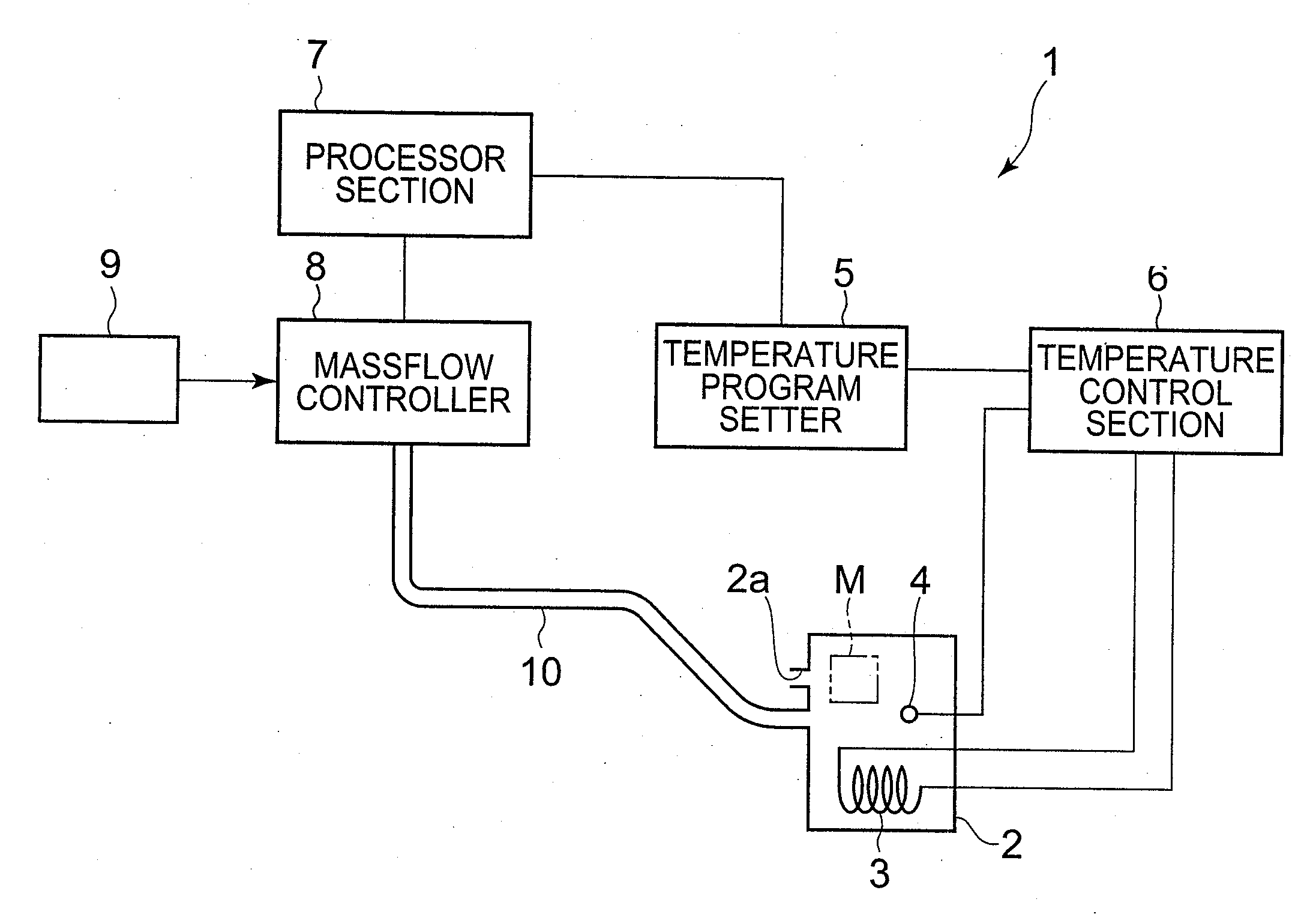
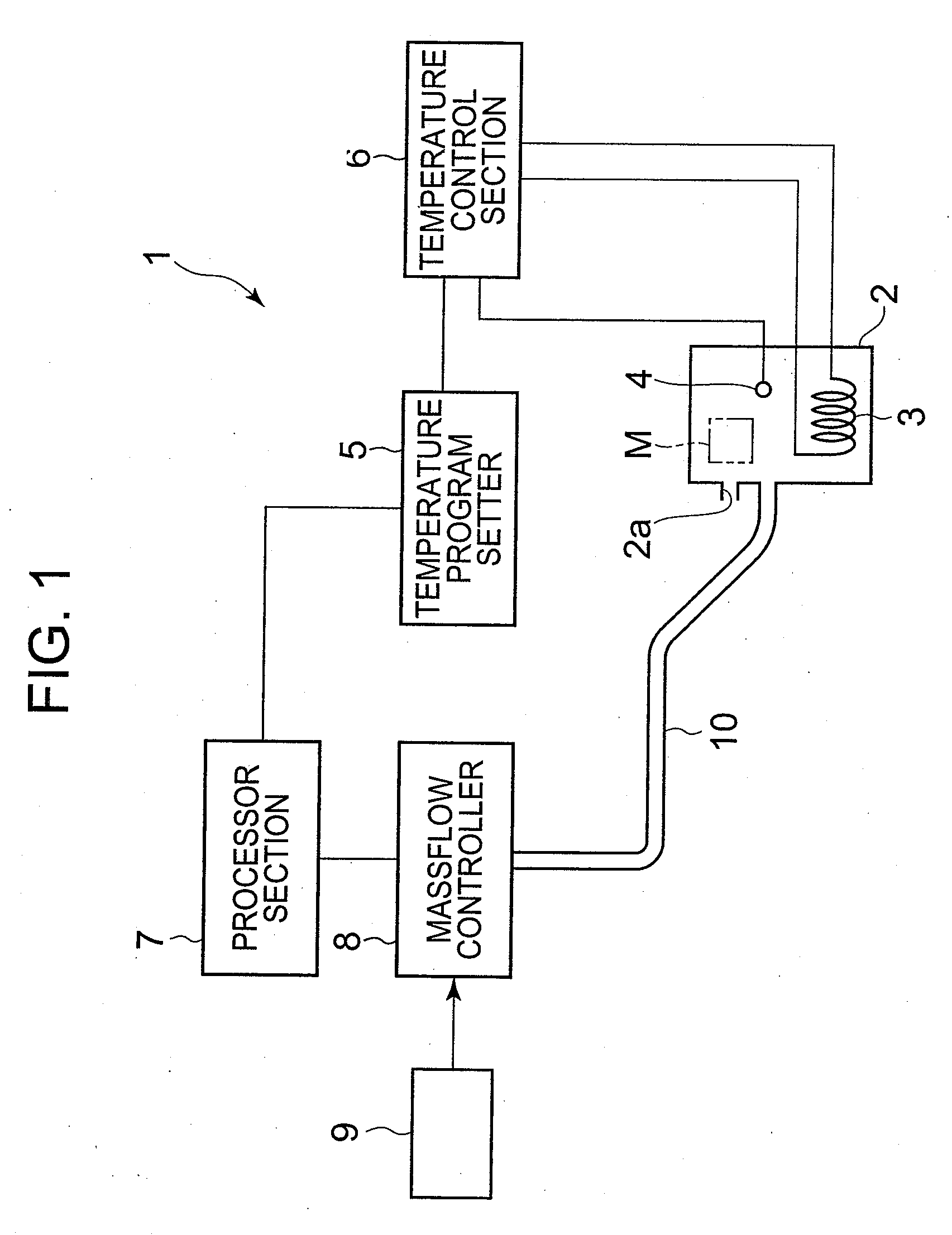
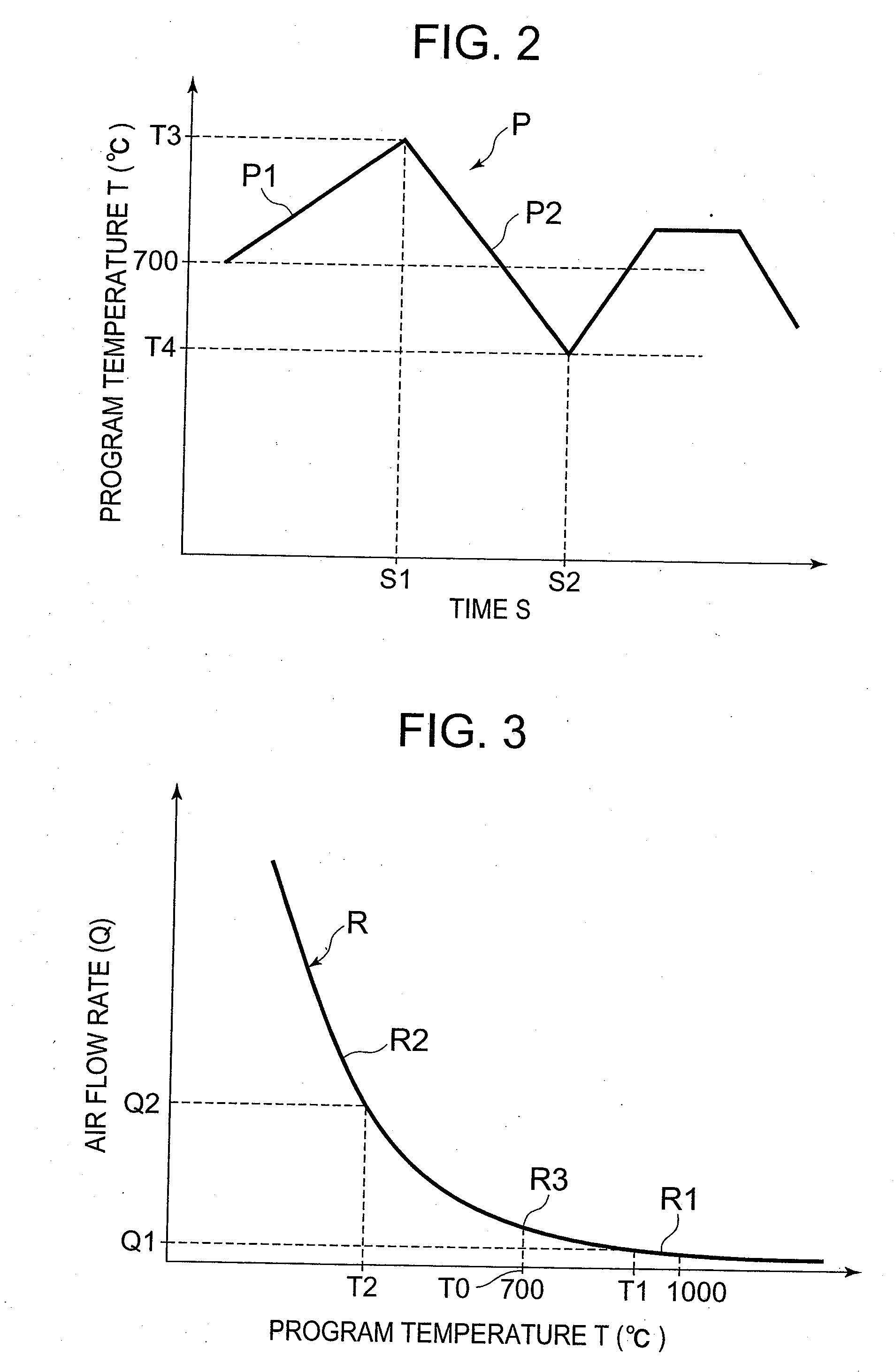
[0027]FIG. 1 is a block diagram explaining a whole epitome of the thermal analysis apparatus by the embodiment of the present invention, FIG. 2 is a diagram showing a temperature program set by a temperature program setter, and FIG. 3 is a graph showing a relation between a program temperature and an air flow rate.

[0028]As shown in FIG. 1, the thermal analysis apparatus by the present embodiment is one adopted in a thermal analysis apparatus 1 such as a differential scanning calorimeter capable of measuring a quantity of egress-and-ingress of a heat by performing a thermal analysis in order to detect a physical property change (structural phase transition, thermal denaturation, fusion, crystallization, or the like) occurring in a matter by a temperature change, a thermobalance detecting a weight change of the matter, and the like.

[0029]Fi...


PUM


Abstract

A thermal analysis apparatus possesses a temperature sensor measuring a temperature of a heating furnace inside, a temperature program setter which can set a temperature program and outputs a temperature program signal, a temperature control section adjusting a supply electric power to a heater in compliance with a difference between the temperature program signal and a detection signal of the temperature sensor, a processor section calculating an air flow rate corresponding to a program temperature, and a mass flow controller which adjusts an air flow rate supplied to the heating furnace inside in compliance with a signal of the air flow rate calculated by the processor section. In the processor section, operation expressions calculating the air flow rate are set so as to differ respectively in a higher temperature side and a lower temperature side than a predetermined boundary temperature.

Description

[0001]This application claims priority under 35 U.S.C. § 119 to Japanese Patent Application Nos. JP2006-232274 filed Aug. 29, 2006, the entire content of which is hereby incorporated by reference.BACKGROUND OF THE INVENTION[0002]1. Field of the Invention[0003]The present invention relates to a thermal analysis apparatus in which a heating furnace is cooled by a supply of a cooling gas.[0004]2. Description of the Related Arts[0005]Hitherto, in the thermal analysis apparatus such as differential scanning calorimeter, an analysis is performed by possessing the heating furnace, accommodating in its inside a sample (specimen), and measuring an egress-and-ingress of a heat of the sample with its heat quantity by changing a temperature of the sample by raising or lowering it using heating and cooling apparatuses. In the thermal analysis apparatus like this, there is one in which the heating furnace is temperature-controlled, e.g., by cooling the heating furnace by supplying a gas, which is...

Claims


Application Information

Patent Timeline
IPC IPC(8): G01N25/00
CPCG01N25/20
Inventor NAGASAWA, KANJINAKATANI, RINTARO
Owner HITACHI HIGH TECH SCI CORP
Why Eureka
Try Eureka