
Nano-skeletal catalyst

a skeletal and catalyst technology, applied in the field of catalysts, can solve the problems of high surface-to-volume ratio, high sintering temperature, and micron-scale pores within the structure produced, and achieve the effect of increasing the total catalytic surface area, and increasing the total surface area

Active Publication Date: 2008-11-13
SDC MATERIALS +1
View PDF106 Cites 76 Cited by
  • Summary
  • Abstract
  • Description
  • Claims
  • Application Information

AI Technical Summary

Benefits of technology

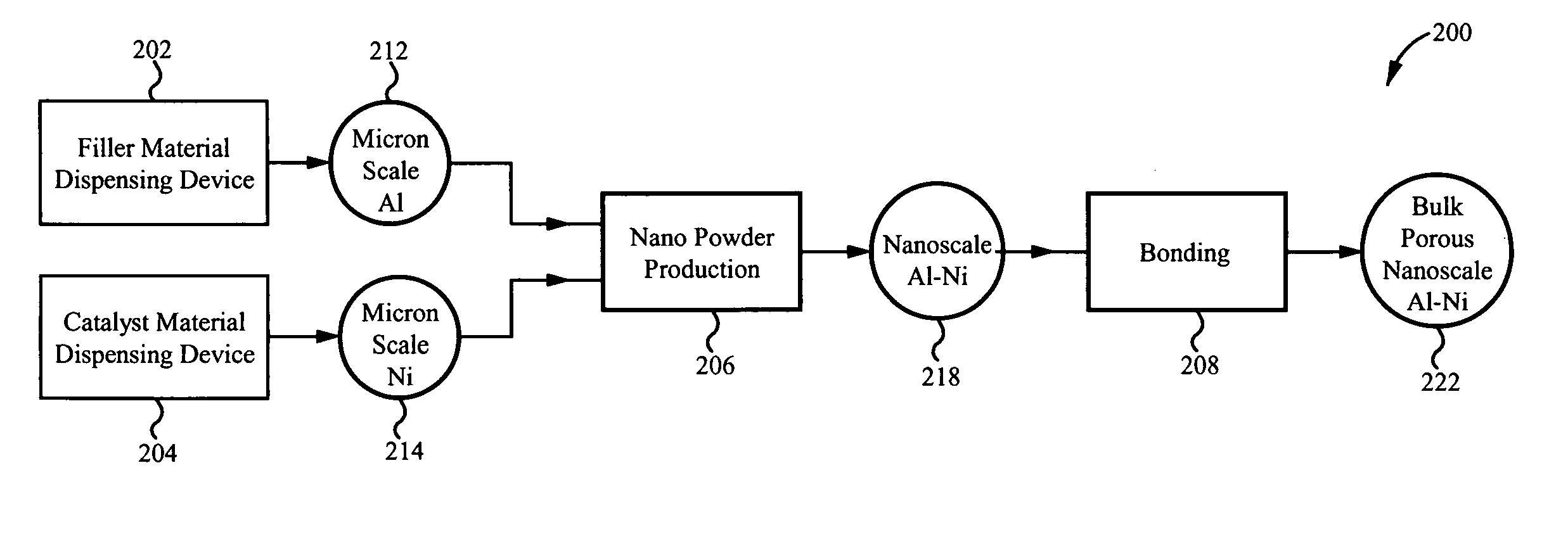
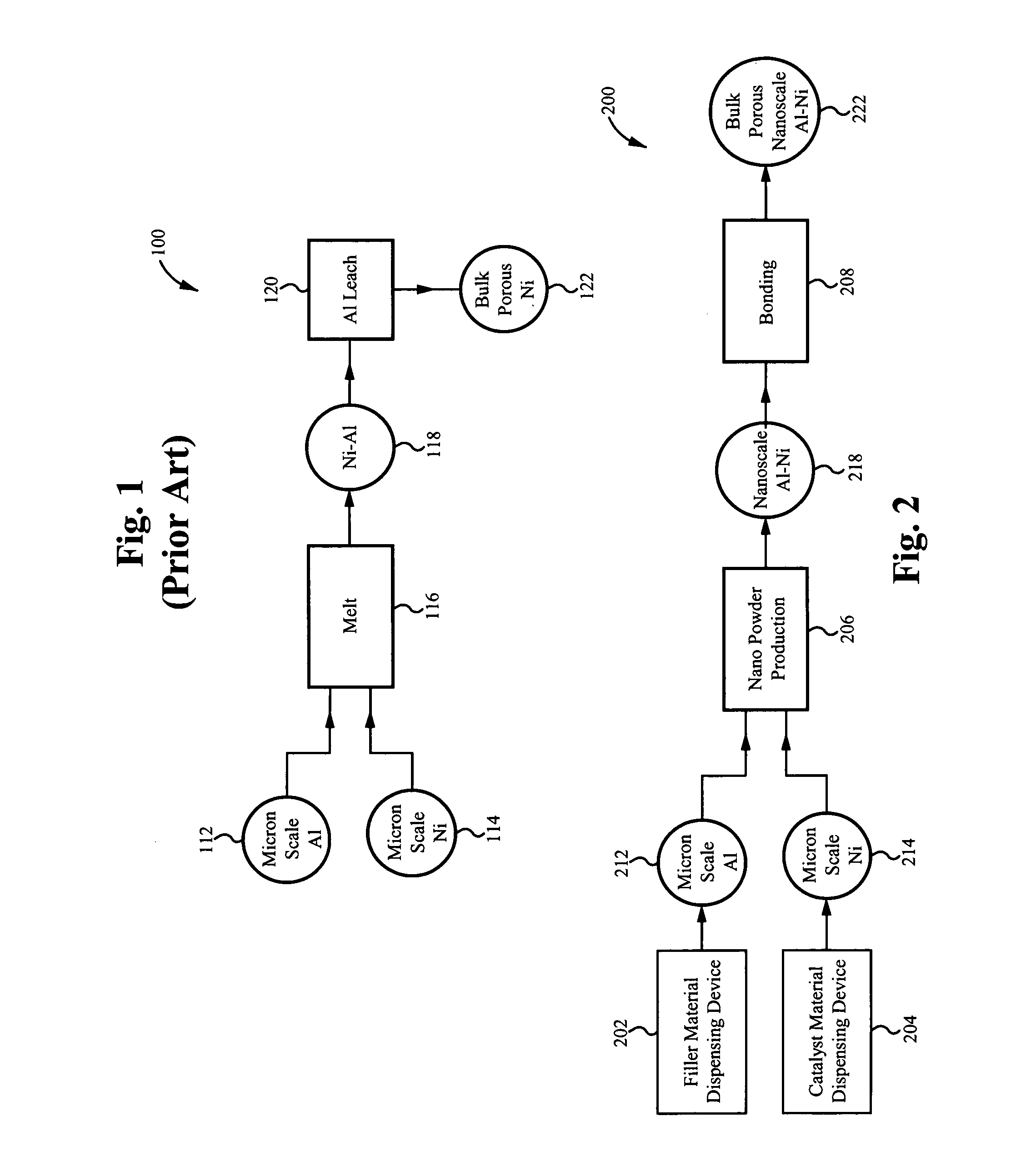
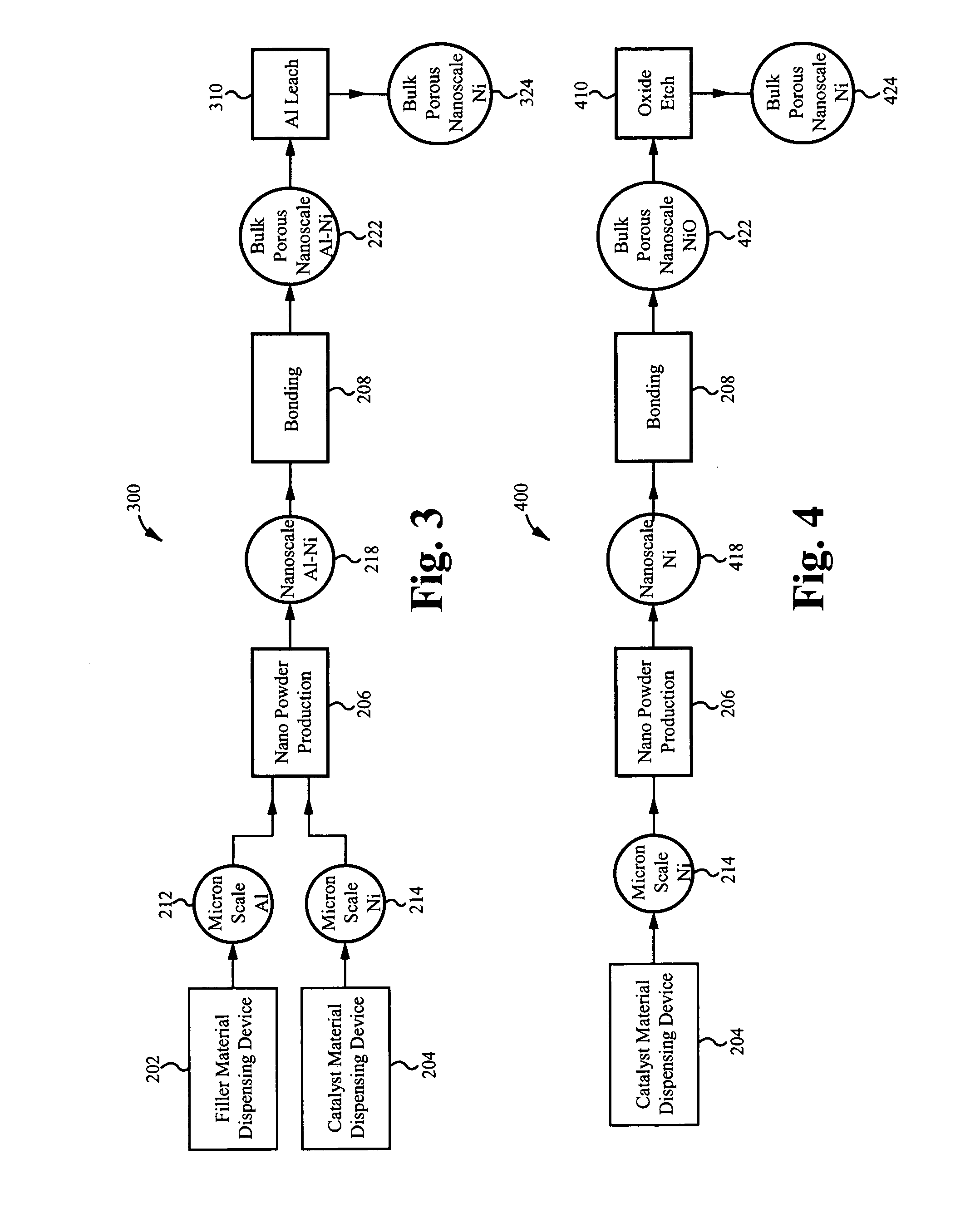
[0020]By forming the bulk structure from nano-sized particles instead of micron-sized (or larger sized) particles, the total catalytic surface area can be significantly increased, given that a nano-particle is significantly smaller than a micron particle thereby allowing for a greater quantity of nano-particles than micron particles. The present invention can increase the total catalytic surface area even more by removing a filler from each particle, thereby creating an internal porosity within each particle, rather than just the bulk porosity between the collection of particles. This internal porosity results in an internal surface area, and therefore, an increase in total surface area. The nano-skeletal structure produced via the present invention preferably has a surface area of at least 10,000 times the surface area of a micron scale structure of the same volume. The increase in surface area results in massive cost savings.

Problems solved by technology

Although small powder catalysts have desirable surface area to volume characteristics, they are only suitable for batch processing and must be isolated after use.
However, these processes involve high sintering temperatures and thus cannot accommodate small, high surface-to-volume-ratio precursor particles (the sintering temperatures are sufficient to destroy the grain structure of the precursor alloy in small particles).
Unfortunately, the smallest pores within the structure produced are micron scale.

Method used


Image

  • Nano-skeletal catalyst
  • Nano-skeletal catalyst
  • Nano-skeletal catalyst

Examples


Embodiment Construction

[0028]The description below concerns several embodiments of the invention. The discussion references the illustrated preferred embodiment. However, the scope of the present invention is not limited to either the illustrated embodiment, nor is it limited to those discussed, to the contrary, the scope should be interpreted as broadly as possible based on the language of the Claims section of this document.

[0029]This disclosure refers to both particles and powders. These two terms are equivalent, except for the caveat that a singular “powder” refers to a collection of particles. The present invention may apply to a wide variety of powders and particles. Additionally, for the purposes of this disclosure, the terms nano-powders and nano-particles refer to powders and particles having an average grain size less than 250 nanometers and an aspect ratio between one and one million.

[0030]The present invention will be readily understood by the following detailed description in conjunction with...


PUM

PropertyMeasurementUnit
grain sizeaaaaaaaaaa
structureaaaaaaaaaa

Abstract

A method of producing a catalyst material with nano-scale structure, the method comprising: introducing a starting powder into a nano-powder production reactor, the starting powder comprising a catalyst material; the nano-powder production reactor nano-sizing the starting powder, thereby producing a nano-powder from the starting powder, the nano-powder comprising a plurality of nano-particles, each nano-particle comprising the catalyst material; and forming a catalyst precursor material from the nano-powder, wherein the catalyst precursor material is a densified bulk porous structure comprising the catalyst material, the catalyst material having a nano-scale structure.

Description

CROSS-REFERENCE TO RELATED APPLICATIONS[0001]The present application claims priority to co-pending U.S. patent application Ser. No. 11 / 110,341, filed on Apr. 19, 2005, entitled, “HIGH THROUGHPUT DISCOVERY OF MATERIALS THROUGH VAPOR PHASE SYNTHESIS” and to co-pending U.S. Provisional Application Ser. No. 60 / 928,946, filed May 11, 2007, entitled “MATERIAL PRODUCTION SYSTEM AND METHOD,” both of which are hereby incorporated by reference as if set forth herein.FIELD OF THE INVENTION[0002]The present invention relates to catalysts, primarily metal catalysts used in fixed bed catalysis of fluid flows, and to methods of reusing catalytic materials. More particularly, the present invention relates to methods of producing a catalyst precursor material with nano-scale structure, methods of producing a skeletal catalyst with nano-scale structure from the precursor, and systems capable of performing these methods.BACKGROUND OF THE INVENTION[0003]Catalysts play many important roles in industry. ...

Claims


Application Information

Patent Timeline
Patent Type & Authority Applications(United States)
IPC IPC(8): B01J23/38B01J21/06B01J23/755B01J23/75B01J23/06B01J23/28B01J23/26C23F1/08B32B37/00B32B38/00
CPCB22F9/12Y10T156/15F28D7/024F28D7/08F28D15/00F28F27/00B22F2999/00B01J19/0013Y10S623/923B01J25/00B01J25/02Y10S623/92B22F2202/13Y10T137/0391Y10T137/2076A61L2/18B22F2203/13B01J19/088B01J37/0018B01J37/349B01J37/06B01J2219/0805B01J2219/0894B01J35/56B01J2/16B01J37/0027B01J2219/0879F28C3/16
Inventor BIBERGER, MAXIMILIAN A.
Owner SDC MATERIALS
Learn More