Dilution limiting device

a limiting device and limiting technology, applied in the direction of auxilary lubrication, pressure lubrication, lubrication elements, etc., can solve the problems of disadvantageous degradation of lubricant oil and limit the dilution of lubricant oil by the fuel, and achieve the effect of reducing the lubricity of the lubricant fluid

Inactive Publication Date: 2008-11-20
PROFORM FINISHING PROD LLC +2
View PDF5 Cites 26 Cited by
  • Summary
  • Abstract
  • Description
  • Claims
  • Application Information

AI Technical Summary

Benefits of technology

[0009]The present invention addresses the above disadvantages. According to one aspect of the present invention, there is provided a dilution limiting device, which includes an anterior chamber; a semipermeable separation film and a posterior chamber. The anterior chamber receives a mixture fluid, in which a lubricant fluid having lubricity and a diluent fluid are mixed. The diluent fluid reduces the lubricity of the lubricant fluid. The semipermeable separation film is permeable to the diluent fluid in the anterio

Problems solved by technology

Thus, it is required to limit dilution of the lubricant oil by the fuel.
However, the fuel component includes a material that has a high boiling point, so that such a mate

Method used


Image

  • Dilution limiting device
  • Dilution limiting device
  • Dilution limiting device

Examples


first embodiment

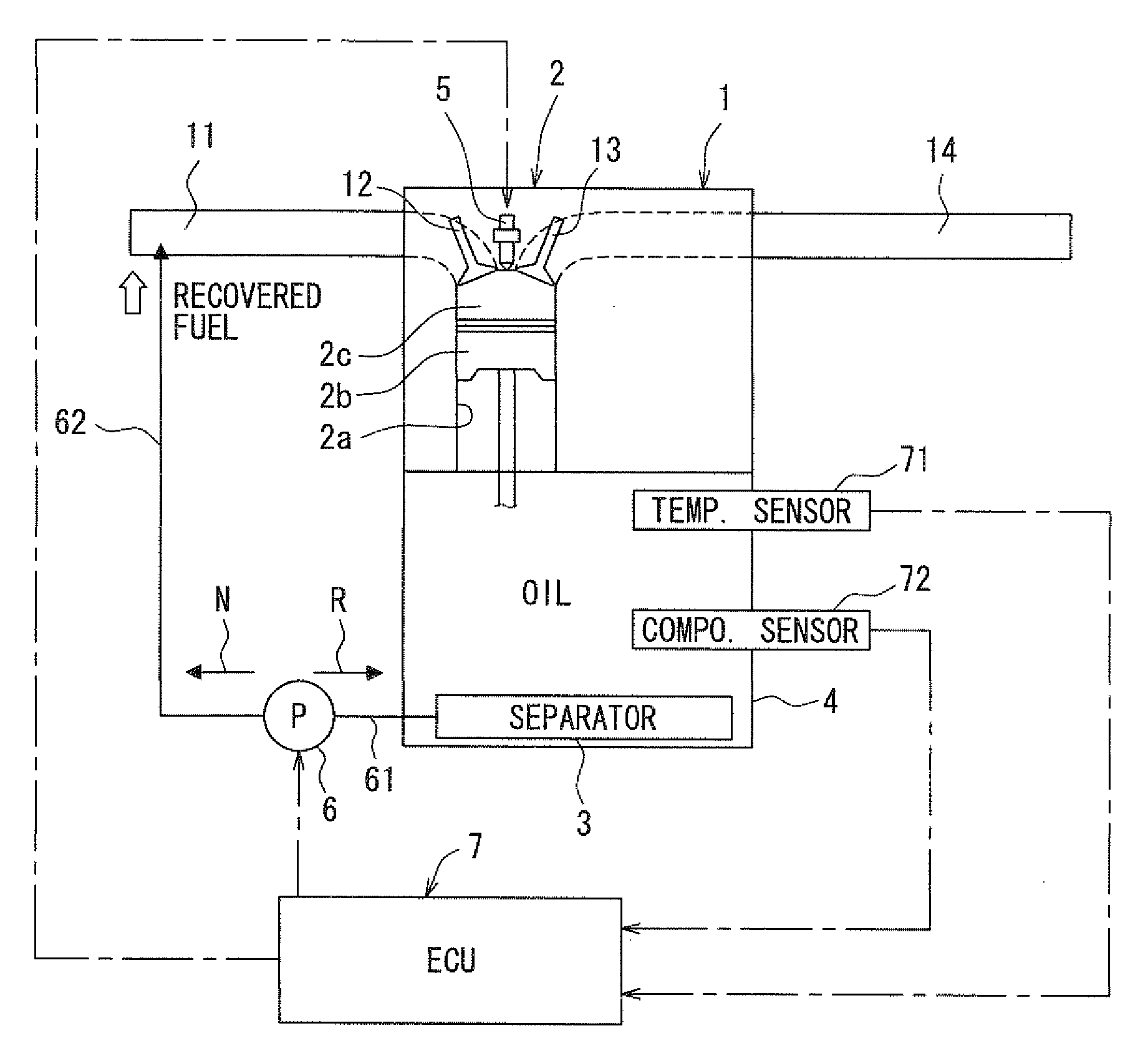
[0024]A lubricant oil filtering system according to a first embodiment of the present invention will be described with reference to FIGS. 1 to 8. FIG. 1 shows a system structure of the lubricant oil filtering system of the internal combustion engine, in which the dilution limiting device is implemented. In this instance, the engine 1 is a multi-cylinder (e.g., four cylinder) engine. In the engine 1, a fuel injection valve 5 is provided in a combustion chamber 2c of each cylinder 2. Fuel, which is stored in a fuel tank, is pumped by a fuel pump to the fuel injection valve 5 through a delivery pipe (not shown).

[0025]The fuel tank stores gasoline as the fuel. The fuel is not limited to the gasoline and may alternatively be, for example, a blended fuel (e.g., gasohol), in which the gasoline is mixed with alcohol.

[0026]An intake pipe 11 is connected to a cylinder bore 2a of each cylinder 2, in which a piston 2b is reciprocably received. At the lower side of the cylinder bore 2a, a crankc...

second embodiment

[0083]Other embodiments of the present invention will be described below. In the following embodiments, the components, which are similar to those of the first embodiment will be indicated by the same reference numerals and will not be described further for the sake of simplicity.

[0084]FIG. 9 shows a second embodiment of the present invention. In the second embodiment, a vibrator (a vibrating means) 8 is provided to vibrate the fuel component separation film 32 and serves as the regenerating means for regenerating the separating function of the fuel component separation film 32.

[0085]As shown in FIG. 9, the vibrator 8 is placed between the fuel component separator 3 and the bottom portion of the oil pan 4.

[0086]The contaminants merely adhere to the fuel component separation film 32. Thus, when the fuel component separation film 32 is vibrated by the vibrator 8 upon receiving a corresponding command from the ECU 7, the contaminants can be shaken off from the area of the fuel componen...

third embodiment

[0088]FIG. 10 shows a third embodiment of the present invention. In the third embodiment, the fuel component separator 3 is further spaced from the bottom wall 4a of the oil pan 4 in comparison to the first embodiment.

[0089]As shown in FIG. 10, the fuel component separator 3 is spaced by a predetermined height h from the bottom wall 4a at the bottom portion of the oil pan 4. In this way, the fuel component separator 3 is sufficiently spaced from the bottom wall 4a at the bottom portion of the oil pan 4 on which the contaminants (e.g., debris, slug) tend to precipitate. Therefore, it is possible to limit adhesion of the precipitated contaminants to the fuel component separator 3, more specifically, the fuel component separation film 32. Furthermore, the fuel component separator 3 is placed in the relatively large space of the oil pan 4, so that the fuel component separation film 32 of the fuel component separator 3 can be made relatively large to improve the separating function of th...


PUM


Abstract

An anterior chamber receives a mixture fluid, in which a lubricant oil and a fuel are mixed. A semipermeable separation film is permeable to the fuel component in the anterior chamber and is not permeable to the lubricant oil in the anterior chamber due to a molecular size difference between the lubricant oil and the fuel, so that the semipermeable separation film selectively separates the fuel component from the mixture fluid. A posterior chamber is placed on an opposite side of the semipermeable separation film, which is opposite from the anterior chamber. The posterior chamber receives the separated fuel component, which is separated by the semipermeable separation film.

Description

CROSS REFERENCE TO RELATED APPLICATION[0001]This application is based on and incorporates herein by reference Japanese Patent Application No. 2007-128566 filed on May 14, 2007.BACKGROUND OF THE INVENTION[0002]1. Field of the Invention[0003]The present invention relates to a dilution limiting device.[0004]2. Description of Related Art[0005]In an internal combustion engine of a direct fuel injection type, fuel is directly injected into a combustion chamber of each cylinder Lubricant oil is applied to form a lubricant oil film between a piston and a wall of the combustion chamber to limit seizing. When fuel adheres to the lubricant oil film, the fuel may possibly be mixed into the lubricant oil and may possibly be circulated in a lubricant oil circuit, which includes an oil pan. Thus, it is required to limit dilution of the lubricant oil by the fuel. Japanese Unexamined Patent Publication No. 2004-340056 teaches a lubricant oil dilution limiting technique.[0006]According to this techni...

Claims


Application Information

Patent Timeline
IPC IPC(8): F16N39/00
CPCF01M1/10F01M2001/165
Inventor ARAKAWA, MIYAOKUROYANAGI, MASATOSHINISHIJIMA, YOSHIAKIKIYOZUMI, YOSHIMICHI
Owner PROFORM FINISHING PROD LLC
Why Eureka
Try Eureka