
Standalone ice dispenser

a stand-alone, dispenser technology, applied in liquid handling, lighting and heating apparatus, packaging goods types, etc., can solve the problems of increasing the overall manufacturing cost of the device, increasing the complexity of the advancing system, and prone to failure of the device, so as to achieve simple ice advancing system, simple ice storage mechanism, and less complex

Active Publication Date: 2008-11-20
MAXWELL TIM
View PDF25 Cites 73 Cited by
  • Summary
  • Abstract
  • Description
  • Claims
  • Application Information

AI Technical Summary

Benefits of technology

[0008]The standalone ice dispenser of the present invention addresses the aforementioned needs in the art by providing a standalone ice dispenser that sells ice at anytime without operator involvement, which dispenser has a relatively simple ice storage mechanism as well as a relatively simple ice advancing system between the storage mechanism and the dispensing mechanism. Simplicity in design of the storage and advancing systems allows for a less complex dispenser thereby allowing for a relatively less expensive machine. By simplifying the storage and advancing systems, the owner of the device is able to schedule service visits less frequently, thereby decreasing the overall operating costs and increasing the up time of the machine.

Problems solved by technology

The problem with current standalone ice dispensers is that the advancing system tends to be relatively complex in design and construction.
This complexity increases the overall manufacturing cost of the device.
Additionally, due to this complexity of the advancing system, the device is more prone to failure.
Increased failure rates result in increased operating costs due to the need to have frequent service visits to each device to maintain proper operation.
Additionally, should the device malfunction, the machine may loose a substantial amount of revenue stream until the problem is resolved ay the next service visit which may be relatively distant in the future.

Method used


Image

  • Standalone ice dispenser
  • Standalone ice dispenser
  • Standalone ice dispenser

Examples


Embodiment Construction

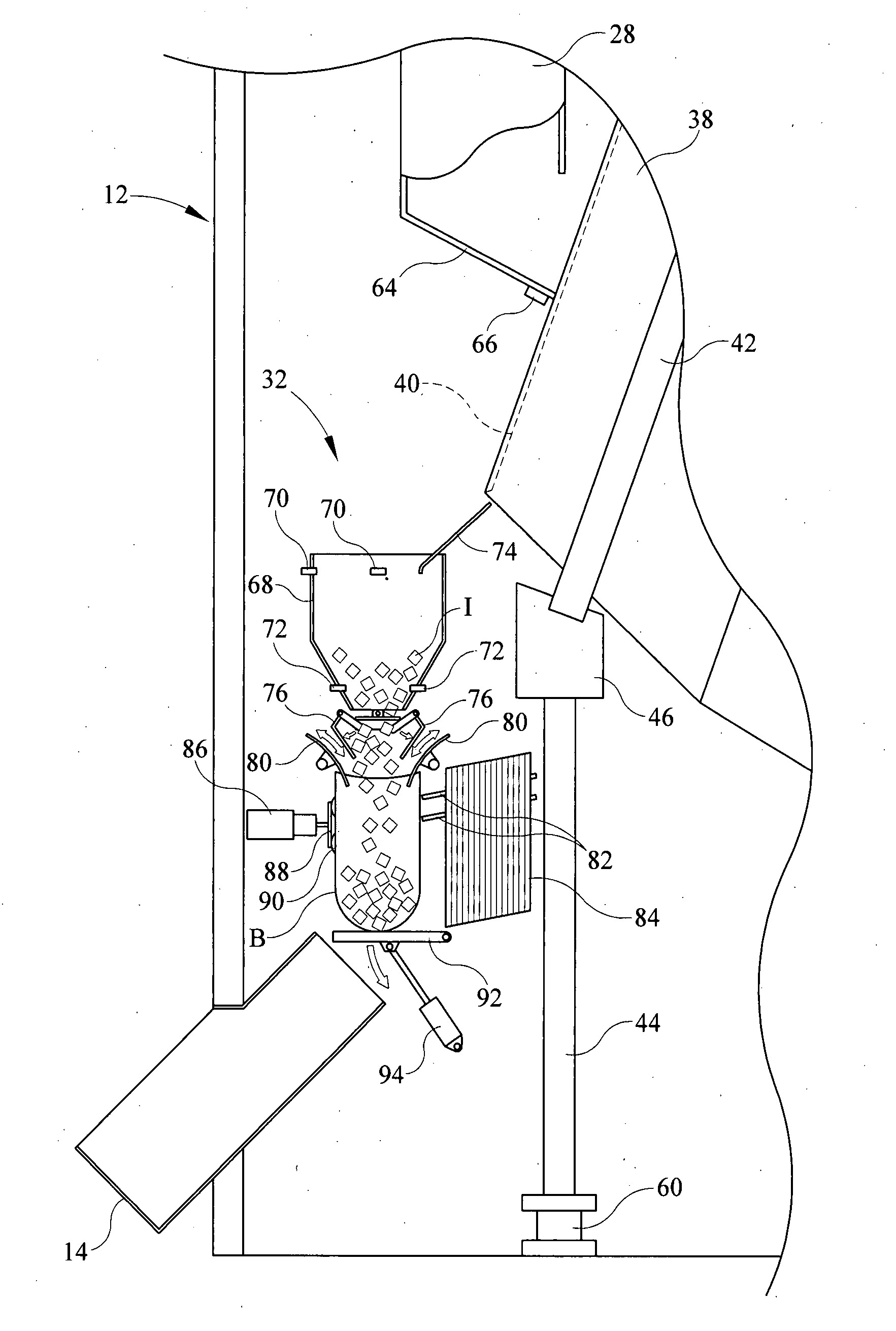
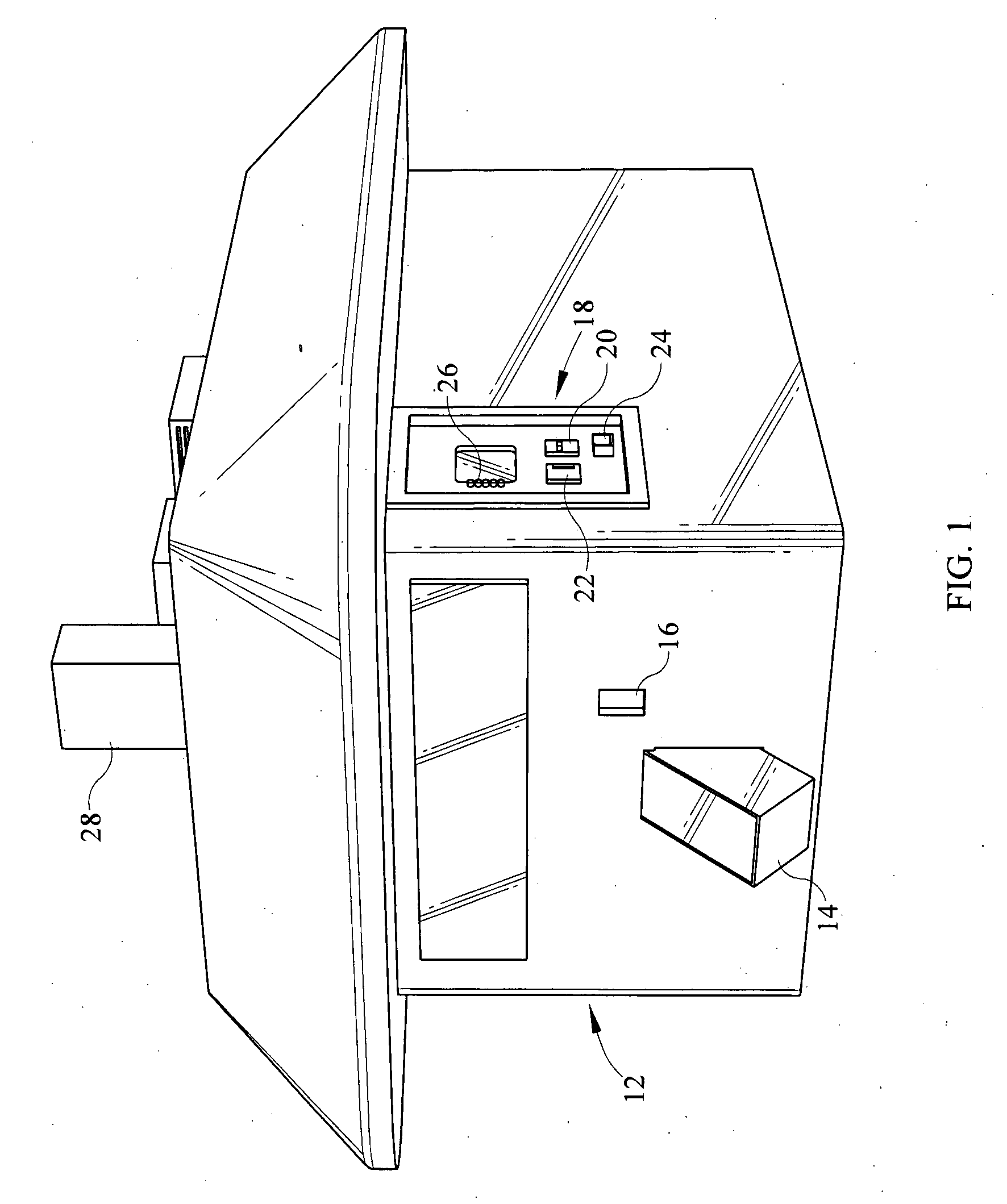
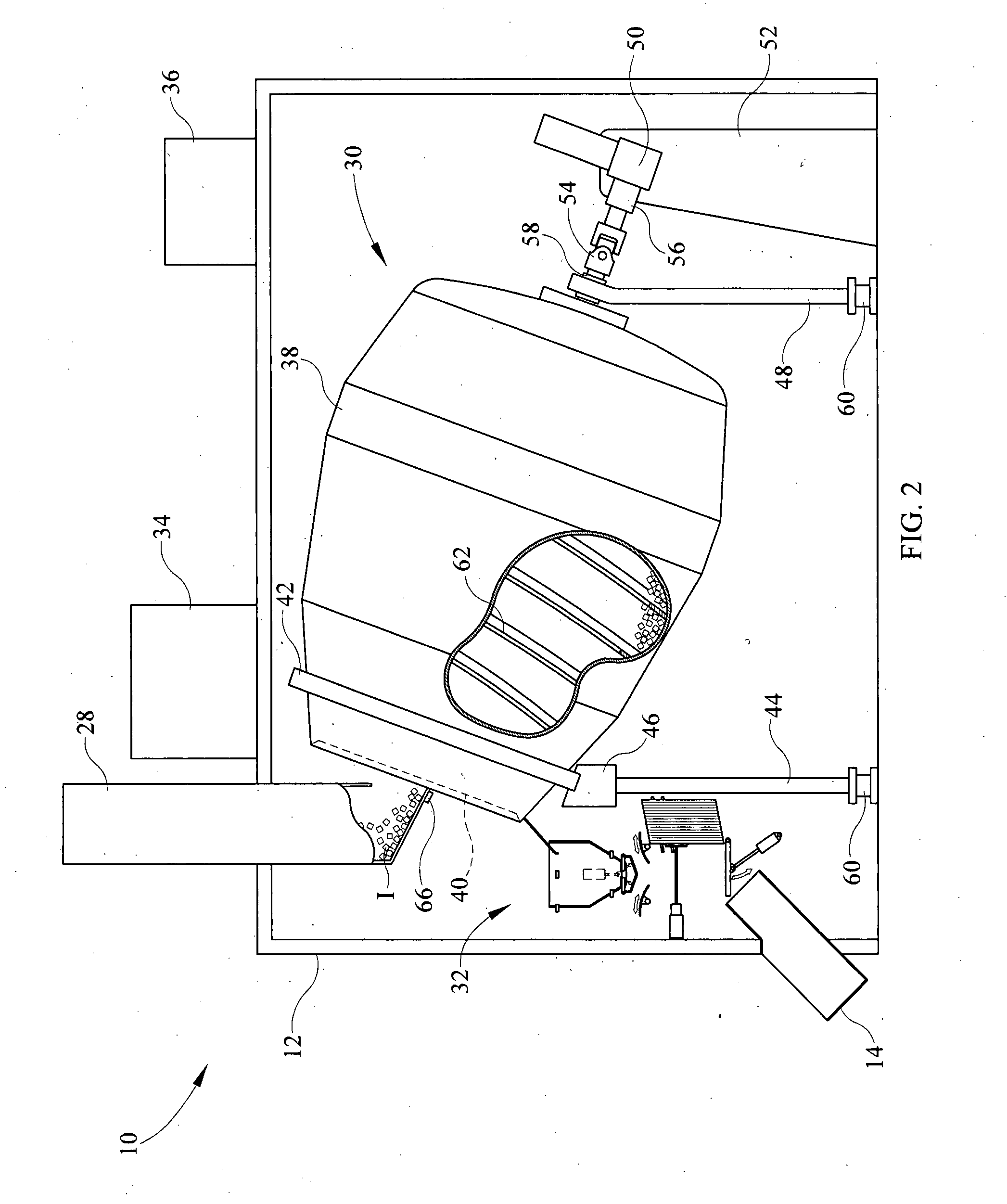
[0016]Referring now to the drawings, it is seen that the standalone ice dispenser of the present invention, generally denoted by reference numeral 10, is comprised of a housing 12 that has a dispensing chute 14, the ice I being delivered to the consumer through the chute 14. A storage window 16 holds twist ties that are used to tie the bag B that is dispensed through the chute 14. Also located on the exterior of the housing 12 is a payment center 18 that has a money acceptor of any appropriate design including a bill acceptor 20 and a coin acceptor 22, a change slot 24, and a selection panel 26 for selecting desired quantities and for allowing other interactions with the device 10. The standalone ice dispenser 10 may also have a credit card or debit card acceptance system (not illustrated) that communicates with an appropriate financial clearing house via a cellular telephone (also not illustrated) for accepting such payments from a consumer. Of course the dispensing chute 14 and th...


PUM

PropertyMeasurementUnit
Weightaaaaaaaaaa
Volumeaaaaaaaaaa

Abstract

A standalone ice dispenser delivers ice in either bagged form or bulk form to a user. The device uses a cone-shaped drum with an upwardly oriented mount that receives and stores the ice which ice is gravitationally delivered to the drum from an ice maker. When ice is to be dispensed, a motor rotates the drum such that a fin within the drum cause ice therein to advance toward and eventually out of the mouth of the drum into either a bagging system or directly out of the device via a chute. Weight sensors attached to the drum determine whether the drum is relatively empty or relatively full and control operation of the ice maker as a result and / or a proximity sensor measures the volume of ice in the drum and controls the operation of the ice maker.

Description

BACKGROUND OF THE INVENTION[0001]1. Field of the Invention[0002]The present invention relates to a standalone ice dispenser that uses a simplified ice advancing mechanism.[0003]2. Background of the Prior Art[0004]Standalone ice dispensers have gained in popularity in recent times. These devices, which are typically placed in a parking lot or similar location, automatically sell ice to consumers without the need for an attendant to be present. The standalone ice dispenser, which is about the size of a large shed, is placed at the desired location and is hooked up to a local water supply and to a source of electricity. Once operational, the ice dispenser manufactures ice, which ice is sold to consumers by having the consumer approach the device and place money into an appropriate receiver, in similar fashion to the operation of a soda machine. Once the funds are received by the machine, a quantity of ice is measured out and is dispensed to the consumer, typically in a bag, however, so...

Claims


Application Information

Patent Timeline
IPC IPC(8): B65B3/16F25C5/18B65B1/32B67D5/08B67D5/64B67D7/08B67D7/84
CPCB65B1/36B65B5/067B65B39/002B65B39/007B65B39/12F25C5/002F25C5/20
Inventor MAXWELL, TIM
Owner MAXWELL TIM
Features
  • Generate Ideas
  • Intellectual Property
  • Life Sciences
  • Materials
  • Tech Scout
  • Unparalleled Data Quality
  • Higher Quality Content
  • 60% Fewer Hallucinations
Learn More