Vehicle Having In-Wheel Motors

a technology of in-wheel motors and in-wheel drives, which is applied in the direction of electric propulsion mounting, electric devices, transportation and packaging, etc., can solve the problems of rear wheels, road follow-up properties of tires, deteriorating road holding properties, etc., and achieves the effect of improving the ground holding performance of front wheels and rear wheels, improving the running ability and riding comfort, and reducing the unsprung mass

Inactive Publication Date: 2008-11-20
KYB CORP +2
View PDF10 Cites 37 Cited by
  • Summary
  • Abstract
  • Description
  • Claims
  • Application Information

AI Technical Summary

Benefits of technology

[0023]According to the present invention, in the vehicle having an internal combustion engine and in-wheel motors, the internal combustion engine is mounted on the front side of the vehicle to drive the front wheels and the in-wheel motors supported to at least one of the unsprung mass of the vehicle and the car body by a buffer mechanism drive the rear wheels, or the internal combustion engine is mounted on the rear side of the vehicle to drive the rear wheels and the in-wheel motors supported to one of the unsprung mass of the vehicle and the car body by the buffer mechanism drive the front wheels. Therefore, on a side where the internal combustion engine is mounted, the sprung mass is increased by the weight of the internal combustion engine whereas on a side opposite to the side where the internal combustion engine is mounted, the in-wheel motors are float mounted to a part around the wheel of the vehicle and the mass of the motors serves as the mass of a dynamic damper. Therefore, the unsprung mass is reduced, thereby making it possible to improve the ground holding performance of the front wheels and the rear wheels as well as the running ability and riding comfort of the vehicle having in-wheel motors.
[0024]As the above buffer mechanism, there is provided a structure such that adjacent plates interconnected by a direct-acting guide mechanism are further interconnected by spring members and damper.
[0025]Particularly when the above buffer mechanism comprises (1) two plates which are interconnected by a direct-acting guide with springs composed of a direct-acting guide comprising a linear bearing and a rod and spring members mated with the direct-acting guide and whose directions are limited to the vertical direction of the vehicle and (2) a damper for interconnecting the two plates, moving in the vertical direction of the vehicle, the buffer mechanism for supporting the motors can be reduced in size while required elastic properties and attenuation characteristics are retained. Thereby, the vertical movement stroke of the motor can be fully ensured and the whole wheel can be reduced in size, whereby a vehicle having in-wheel motors having excellent running ability and riding comfort can be realized and a vehicle having in-wheel motors with high space efficiency can also be realized.

Problems solved by technology

When the unsprung mass increases, a change in the ground load of each tire when running on an uneven road becomes larger, thereby deteriorating the road holding properties, that is, road follow-up properties of the tire.
On the other hand, as the sprung mass becomes small and the unsprung mass becomes large on the rear wheel side, the same drive force cannot be distributed to the front wheels and the rear wheels, thereby reducing running ability.
Further, as vibration above the spring increases, riding comfort deteriorates.
Therefore, also in this case, the same drive force cannot be distributed to the front wheels and the rear wheels, thereby reducing running ability and riding comfort.

Method used


Image

  • Vehicle Having In-Wheel Motors
  • Vehicle Having In-Wheel Motors
  • Vehicle Having In-Wheel Motors

Examples


Embodiment Construction

[0036]Preferred embodiments of the present invention will be described hereinunder with reference to the accompanying drawings.

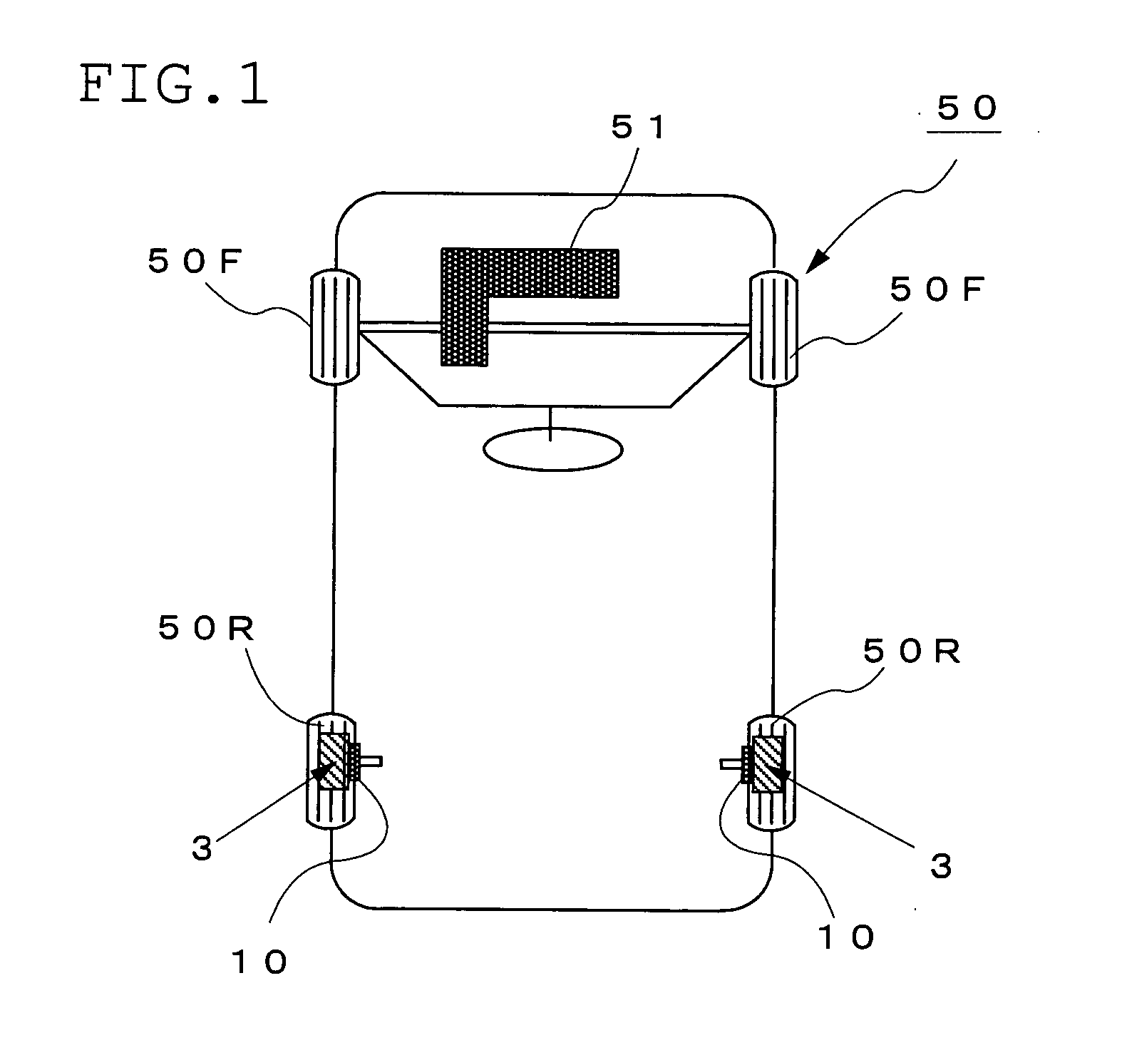
[0037]FIG. 1 is a diagram showing the outline of a vehicle 50 having rear wheel auxiliary driving motors according to a preferred embodiment of the present invention. In the vehicle 50 having rear wheel auxiliary driving motors, an internal combustion engine 51 is mounted on the front side of the vehicle to drive front wheels 50F and 50F and auxiliary driving in-wheel motors 3 are mounted to rear wheels 50R and 50R to drive the rear wheels 50R and 50R. In this embodiment, the above in-wheel motors 3 are connected to the non-rotating sides (vehicle unsprung mass) of the rear wheels 50R and 50R by buffer mechanisms 10.

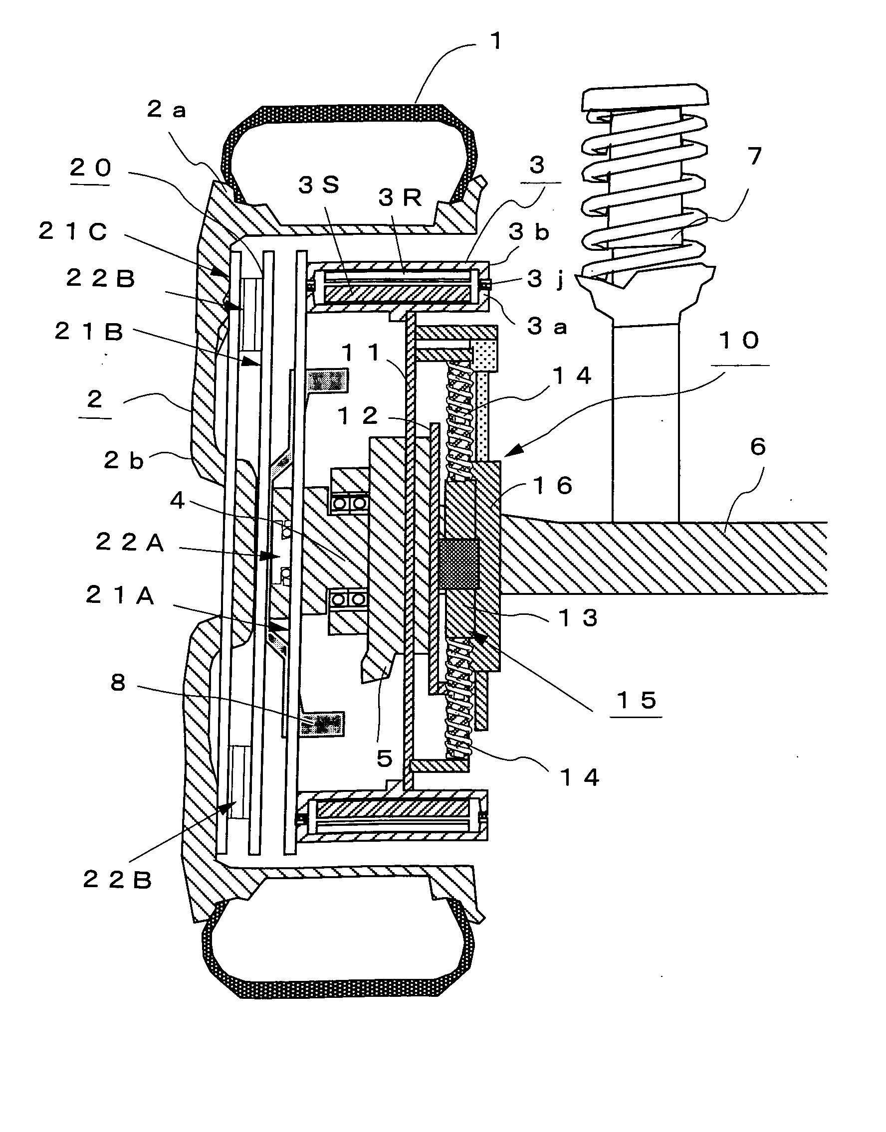
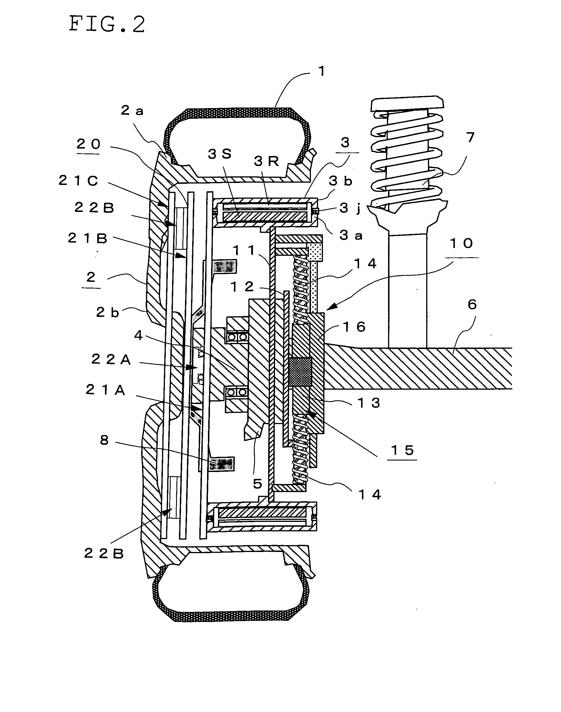
[0038]FIG. 2 shows the details of the rear wheel to which the above in-wheel motor 3 is mounted. In FIG. 2, reference numeral 1 denotes a tire, 2 a wheel comprising a rim 2a and a wheel disk 2b, 3 an outer rotor type in-wheel motor which comprise...


PUM


Abstract

A vehicle having in-wheel motors, wherein when the in-wheel motors are mounted on the vehicle driven by the torque of an internal combustion engine, the in-wheel motors (3) are mounted on wheels on one side of the vehicle opposite to the other side on which the internal combustion engine (51) is mounted. The non-rotating side of the motor and the knuckle (5) are supported by a buffer mechanism (10) having plates (11) and (12) connected to each other by a direct-acting guide (15) with springs composed of a direct-acting guide (13) comprising a linear bearing (13A) and a rod (14) and spring members 14 and 14 moving in the vertical direction of the vehicle and mated with the direct-acting guide (13) and a damper (16) for interconnecting the plates (11) and (12), moving in the vertical direction of the vehicle to support the motor (3) to either one or both of the unsprung mass of the vehicle and the car body by means of the buffer mechanism (10). Thus, the running ability and riding comfort of the vehicle having in-wheel motors can be improved.

Description

BACKGROUND OF THE INVENTION[0001]1. Field of the Invention[0002]The present invention relates to a vehicle having in-wheel motors and, particularly, to the arrangement of in-wheel motors and an internal combustion engine in a vehicle having an internal combustion engine for driving the vehicle.[0003]2. Description of the Prior Art[0004]As a vehicle having an internal combustion engine for driving front wheels or rear wheels, there has been known a vehicle having auxiliary driving motors in which the front wheels or the rear wheels are driven by an internal combustion engine and auxiliary driving electric motors are mounted to the rear wheels or front wheels to assist the driving force of the vehicle. FIG. 9(a) shows an example of a vehicle 60 having rear wheel auxiliary driving motors. In the vehicle 60 having rear wheel auxiliary driving motors, a generator 63 is mounted to an internal combustion engine 62 for driving the front wheels 60F and 60F, and auxiliary driving electric mot...

Claims


Application Information

Patent Timeline
Patent Type & Authority Applications(United States)
IPC IPC(8): B60K1/00B60G13/16B60G3/01B60K6/26B60K6/40B60K6/485B60K6/52B60K7/00B60K17/04B60K17/356B60L50/16
CPCB60G3/01B60G2204/30B60K6/48B60K6/52B60K7/0007B60K17/046B60K2007/0038B60K2007/0092Y02T10/6221Y02T10/6265B60L2220/44B60L2220/46Y02T10/62
Inventor SUZUKI, YASUHIROTASHIRO, KATSUMIKUROKAWA, HISASHINAKAMURA, YOSHINARITAKAHASHI, KIMIO
Owner KYB CORP
Why Eureka
Try Eureka