Semiconductor Heterostructure

a technology of semiconductors and heterostructures, applied in the field of semiconductor heterostructures, can solve the problems of increasing the capture time , reducing the capture efficiency of devices, and less effective coupling with localized states inside narrow bandgap layers, etc., and achieve the effect of enhancing the total light generation capability

Inactive Publication Date: 2008-11-20
OPTOGAN OY
View PDF22 Cites 22 Cited by
  • Summary
  • Abstract
  • Description
  • Claims
  • Application Information

AI Technical Summary

Benefits of technology

[0008]One specific objective of the invention is to disclose a new type of strained semiconductor heterostructure with enhanced total light generating capability, the heterostructure being formed e.g. from pyroelectric semiconductor materials as nitrides of group III metals and their alloys, or from nitrogen containing arsenides and phosphides of group III metals.

Problems solved by technology

Therefore, the probability for carrier to be inside the narrow bandgap region decreases, which results in less effective coupling with localized state inside narrow bandgap layer and in increasing of the capture time τ. In result, the capture efficiency of the device drops and maximum of the efficiency ηext vs. injection current is located far below the typical device operating current.
However, presence of such barrier increases electron and hole reflection, making this solution not optimal.
One disadvantage of this solution, however, is that the tunneling of carriers in this case is not resonant, and therefore for any reasonable barrier thickness the reflection of carriers from the barriers significantly decreases efficiency of carrier capture into the light generation region.
In fact, it is hard to realize thick high quality layer on the basis of lattice mismatched semiconductor materials.
However, for the materials where the concentration of active doping centers in one of the emitters is limited by fundamental material properties, excessive doping of the other emitter breaks the balance of electron and hole injection currents at the light generation layer resulting in reduced injection efficiency.
Such non-direct recombination leads to a decrease of device radiative quantum efficiency.
However, such small thickness, as we mentioned above, results in non-effective carrier capture.
These fluctuations can lead to formation of “holes” in the light generation layers, which act as non-radiative recombination centers, thus additionally reducing device efficiency.
As a conclusion, the polarization induced built-in electric field limits both radiative efficiency and capture rate.
However, in pyroelectric materials spontaneous polarization also exists, which is non-zero even in relaxed or lattice-matched layers.

Method used


Image

  • Semiconductor Heterostructure
  • Semiconductor Heterostructure
  • Semiconductor Heterostructure

Examples


Embodiment Construction

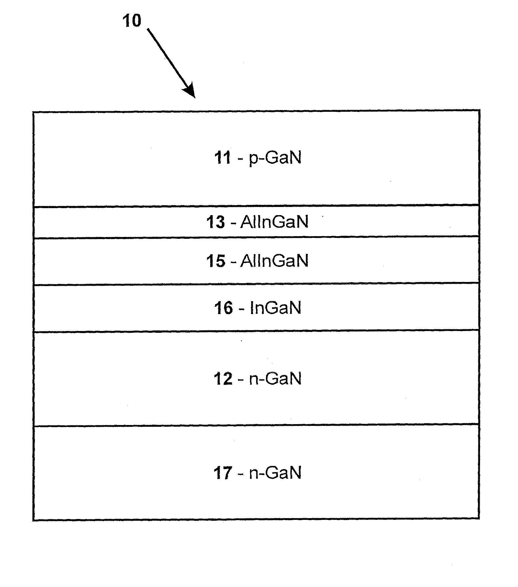
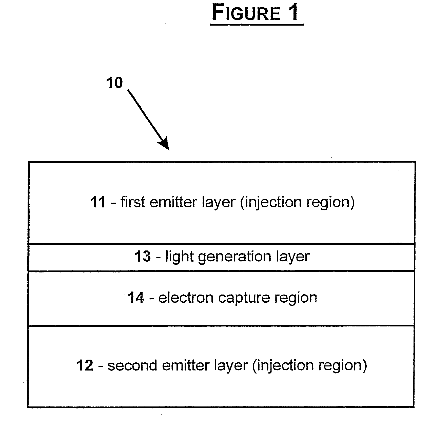
[0032]In FIG. 1 a cross-sectional schematic view of the semiconductor heterostructure is shown. The heterostructure, which is generally designated by 10, comprises an injection region consisting of a first emitter layer 11 and a second emitter layer 12, a light generation layer 13, and an electron capture region 14 consisting of a capture layer and a confining layer.

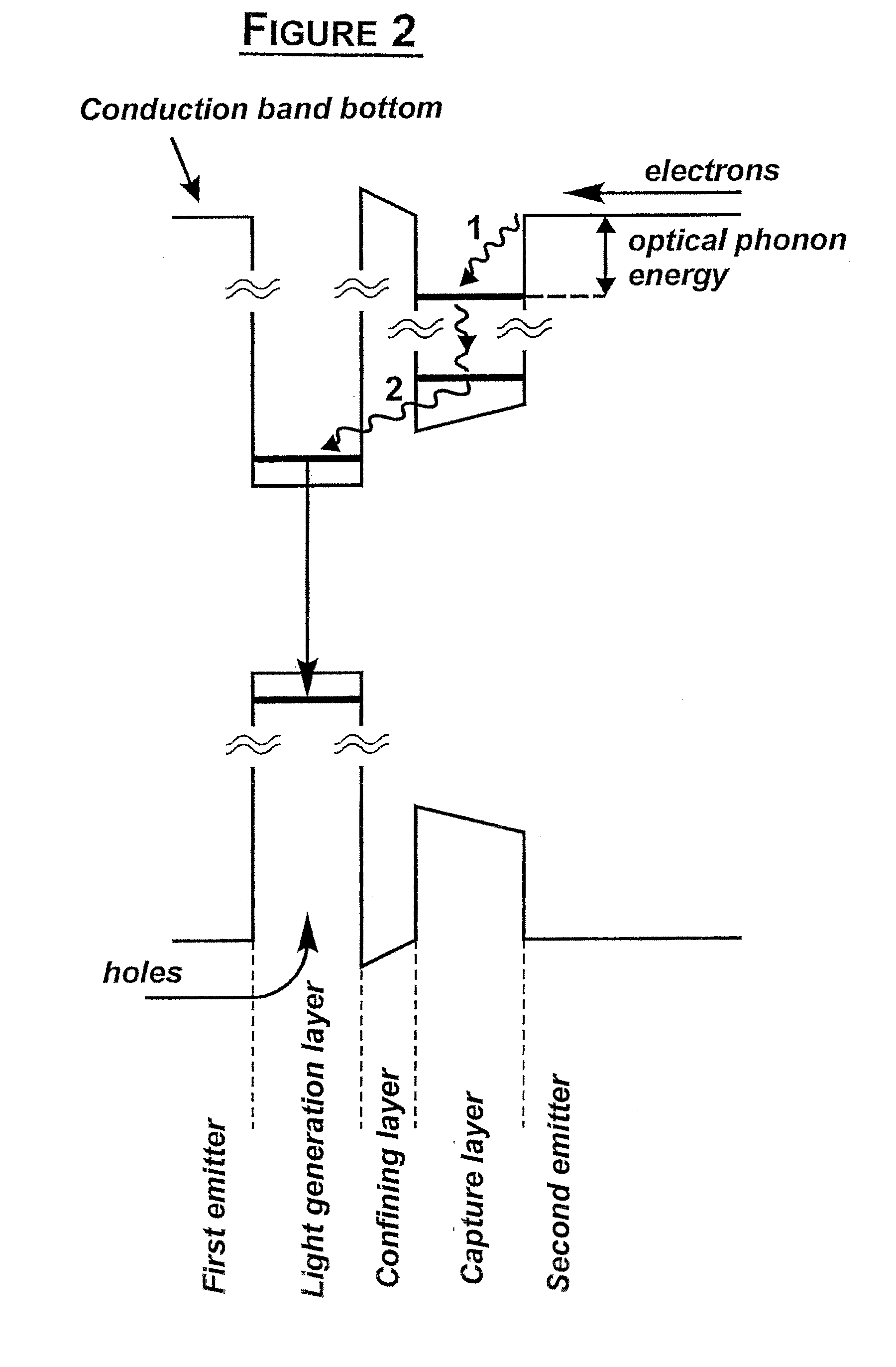
[0033]FIG. 2 represents a schematic energy band diagram of the heterostructure shown in FIG. 1. The capture region is a narrow bandgap layer adjacent to the second emitter layer. The layer with a wide bandgap between the capture and light generation layers is the confining layer. Widths and compositions of the capture and confining layers are adjusted to provide energy difference between one of the localized electron energy levels of the capture layer and the conduction band bottom in the electron emitter equal to the optical phonon energy. The capture of electrons into the narrow bandgap capture layer occurs due to inte...


PUM


Abstract

A strained semiconductor heterostructure (10) comprises an injection region comprising a first emitter layer (11) having p-type conductivity and a second emitter layer (12) having n-type conductivity, and a light generation layer (13) positioned between the first emitter layer (11) and the second emitter layer (12). An electron capture region (14) is positioned between the light generation layer (13) and the second emitter layer (12), said electron capture region comprising a capture layer (16) adjacent to the second emitter layer, and a confining layer (15) adjacent to said electron capture layer. According to the present invention, the widths and materials of the confining and capture layers (15, 16) are selected to provide energy difference between one of localized energy levels for electrons in the capture layer (16) and the conduction band bottom of the second emitter layer (12) equal to the energy of the optical phonon.

Description

FIELD OF THE INVENTION[0001]The present invention relates to a semiconductor heterostructure for light emitting devices, particularly a structure formed of lattice mismatched semiconductor materials. The heterostructure comprises an injection region consisting of two emitters, a light generation layer, and an electron capture region. In particular, the heterostructure can be made of pyroelectric materials, particularly nitrides of group III metals and their alloys. The heterostructure can also be made of nitrogen containing arsenides and phosphides of group III metals.BACKGROUND OF THE INVENTION[0002]The external quantum efficiency of a light emitting diode, herein referred to as LED, can be defined as:ηext=γ·ηcap·ηint·ηout,where γ is the injection efficiency, ηcap is the efficiency of carrier capture into light generation region, ηint is the radiative efficiency provided by radiative recombination of carriers inside the light generation region, ηout is the light extraction efficien...

Claims


Application Information

Patent Timeline
Patent Type & Authority Applications(United States)
IPC IPC(8): H01L33/00H01L33/06H01L33/32
CPCB82Y20/00H01L33/32H01L33/06
Inventor ODNOBLYUDOV, MAXIM A.BOUGROV, VLADISLAV E.
Owner OPTOGAN OY
Why Eureka
Try Eureka