Power Converter

a power converter and converter technology, applied in the direction of dynamo-electric converter control, motor/generator/converter stopper, dc circuit to reduce harmonics/ripples, etc., can solve the problems of harmonic leakage current and shaft voltage, noise terminal voltage, conduction noise, etc., to prevent magnetic saturation and prevent magnetic saturation

Active Publication Date: 2008-11-20
DAIKIN IND LTD
View PDF16 Cites 24 Cited by
  • Summary
  • Abstract
  • Description
  • Claims
  • Application Information

AI Technical Summary

Benefits of technology

[0022]The first invention produces the distinctive effects of preventing magnetic saturation of the common mode choke coil of the common mode filter, which in turn can achieve size reduction of the common mode choke coil.
[0023]The second invention produces the distinctive effects of preventing magnetic saturation of the common mode choke coil of the common mode filter, which in turn can achieve size reduction of the common mode choke coil.

Problems solved by technology

This common mode voltage Vinv results in harmonic leakage current and a shaft voltage when driving a motor by an inverter.
The harmonic leakage current results in a conduction noise, which mainly causes a noise terminal voltage.
However, when the magnetic flux density of the common mode choke coil exceeds a saturation magnetic flux density Bmax, the inductance is reduced drastically, so that it no longer serves as a common mode filter.

Method used


Image

  • Power Converter
  • Power Converter
  • Power Converter

Examples


Embodiment Construction

[0024]Hereinafter, an embodiment of this invention will be described in detail with reference to the accompanying drawings.

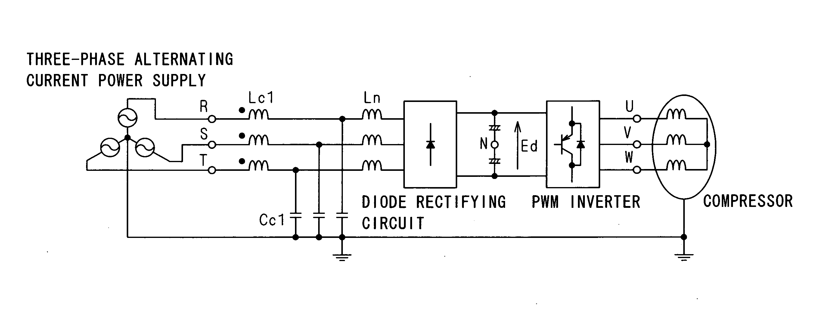
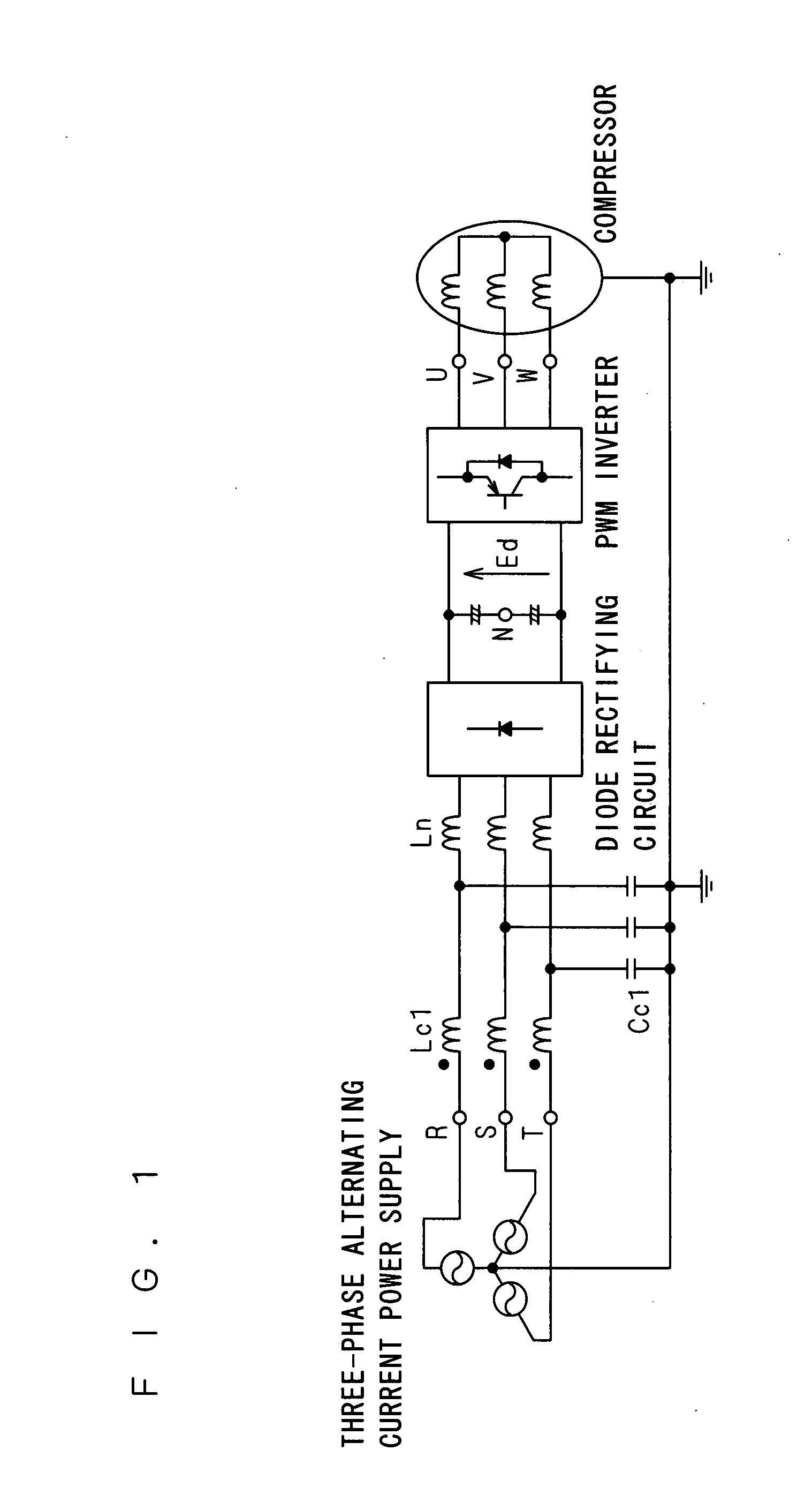
[0025]FIG. 12 is a schematic diagram showing the configuration of a compressor-driving-motor driving system into which an embodiment of a power converter of this invention is incorporated.

[0026]This compressor-driving-motor driving system includes a PWM rectifying circuit 2 having each input terminal connected to each phase output terminal of a Y-connected three-phase alternating current power supply 1 via a common mode choke coil Lc1 and a reactor Ln in series, a pair of capacitors 3 having capacities equal to each other connected in series between output terminals of the PWM rectifying circuit 2, a PWM inverter 4 having an input terminal to which a voltage between terminals of the series connection circuit of the pair of capacitors 3 is applied, and a compressor driving motor 5 to which the output of the PWM inverter 4 is supplied. And, it includes a capacitor...


PUM


Abstract

A power converter is provided with a rectifying circuit, an inverter circuit, and a common mode filter including a common mode choke coil and a capacitor. The switching frequency of a PWM rectifying circuit is set at three times the switching frequency of a PWM inverter. Alternatively, the resonance frequency of the common mode filter is set at twice the carrier frequency of the rectifying circuit or the PWM inverter circuit or more.

Description

TECHNICAL FIELD[0001]This invention relates to a power converter including a PWM rectifying circuit, a PWM inverter circuit, and a common mode filter including a common mode choke coil and a capacitor.BACKGROUND ART[0002]A power converter including a PWM rectifying circuit, a PWM inverter circuit, and a common mode filter including a common mode choke coil and a capacitor has conventionally been presented (cf. Patent document 1).[0003]FIG. 1 is an electric circuit diagram showing a motor driving system for driving a motor via a power converter formed by a diode rectifying circuit and a PWM inverter circuit.[0004]This motor driving system rectifies a three-phase ac voltage to a dc voltage in the diode rectifying circuit, and carries out pulse width modulation by switching devices of the PWM inverter circuit by comparing a triangular wave signal which is a carrier wave and a modulation wave, to thereby output an ac voltage of a desired voltage and frequency and supply it to the motor....

Claims


Application Information

Patent Timeline
Patent Type & Authority Applications(United States)
IPC IPC(8): H02P6/00H02M5/42H02M7/12H02M7/48
CPCH02M1/126H02M5/4585
Inventor KAWASHIMA, REIJIKOYAMA, YOSHITSUGU
Owner DAIKIN IND LTD
Why Eureka
Try Eureka