
Liquid crystal display device and driving method thereof

a liquid crystal display and driving method technology, applied in static indicating devices, non-linear optics, instruments, etc., can solve the problems of dc image sticking, image sticking, and degrading the display quality of moving image devices, so as to prevent dc image sticking and flickering, and enhance display quality

Active Publication Date: 2008-11-20
LG DISPLAY CO LTD
View PDF4 Cites 32 Cited by
  • Summary
  • Abstract
  • Description
  • Claims
  • Application Information

AI Technical Summary

Benefits of technology

[0012]An advantage of the present invention is to provide a liquid crystal display device and a driving method thereof, which are capable of preventing direct current (DC) image sticking and flicker, thereby achieving an enhancement in display quality.
[0013]Additional advantages and features of the invention will be set forth in part in the description which follows and in part will become apparent to those having ordinary skill in the art upon examination of the following or may be learned from practice of the invention. The advantages of the invention may be realized and attained by the structure particularly pointed out in the written description and claims hereof as well as the appended drawings.
[0014]To achieve these and other advantages and in accordance with the purpose of the invention, as embodied and broadly described herein, a liquid crystal display device includes: a liquid crystal display panel formed with a plurality of data lines and a plurality of gate lines, the liquid crystal display panel having a plurality of liquid crystal cells; a frame rate adjusting circuit for controlling a frame rate such that the frame rate is maintained at a 1-fold rate in frame periods other than an Nth frame period (“N” is a multiple of 8 or more), while being increased to an “i”-fold-accelerated rate (“i” is a positive integer of 2 or more) in the Nth frame period, to output reference timing signals in the frame periods other than the Nth frame period, and to output accelerated timing signals in the Nth frame period; a timing controller for generating data timing control signals and gate timing control signals in response to at least one of each reference timing signal and each accelerated timing signal; a logic circuit for accelerating a frequency of a polarity control signal to determine a polarity of a data voltage to be supplied to the liquid crystal cells, in the Nth frame period, the polarity control signal being included in the data timing control signals; a data driving circuit for generating the data voltage in response to the data timing control signals including the polarity control signal; and a gate driving circuit for supplying a scan pulse to the gate lines in response to the gate timing control signals.
[0015]The Nth frame period may comprise at least one first subframe period, in which a data voltage having a polarity opposite to the Nth frame period is supplied to the liquid crystal cells, and at least one second subframe period, in which a data voltage having the same polarity as the Nth frame period is supplied to the liquid crystal cells.
[0016]The frame rate adjusting circuit may comprise a frame determining circuit for determining a frame period, based on the reference timing signals, a timing signal multiplying circuit for multiplying the reference timing signals by the “i”-fold, to generate the accelerated timing signals, and a multiplexer for outputting the accelerated timing signals in the Nth frame period, while outputting the reference timing signals in the frame periods other than the Nth frame period, under a control of the frame determining circuit.
[0017]The logic circuit may comprise a frame counter for counting a gate start pulse indicating a start of the scan pulse, to count a number of frames, an inverter for generating an inverting signal indicating a point of time when the polarity control signal should be inverted in phase in the Nth frame period, in accordance with an output from the frame counter, an exclusive OR gate for exclusively ORing a reference polarity control signal generated from the timing controller and the inverting signal, to generate the polarity control signal, and a multiplexer for selectively outputting the reference polarity control signal or the polarity control signal.

Problems solved by technology

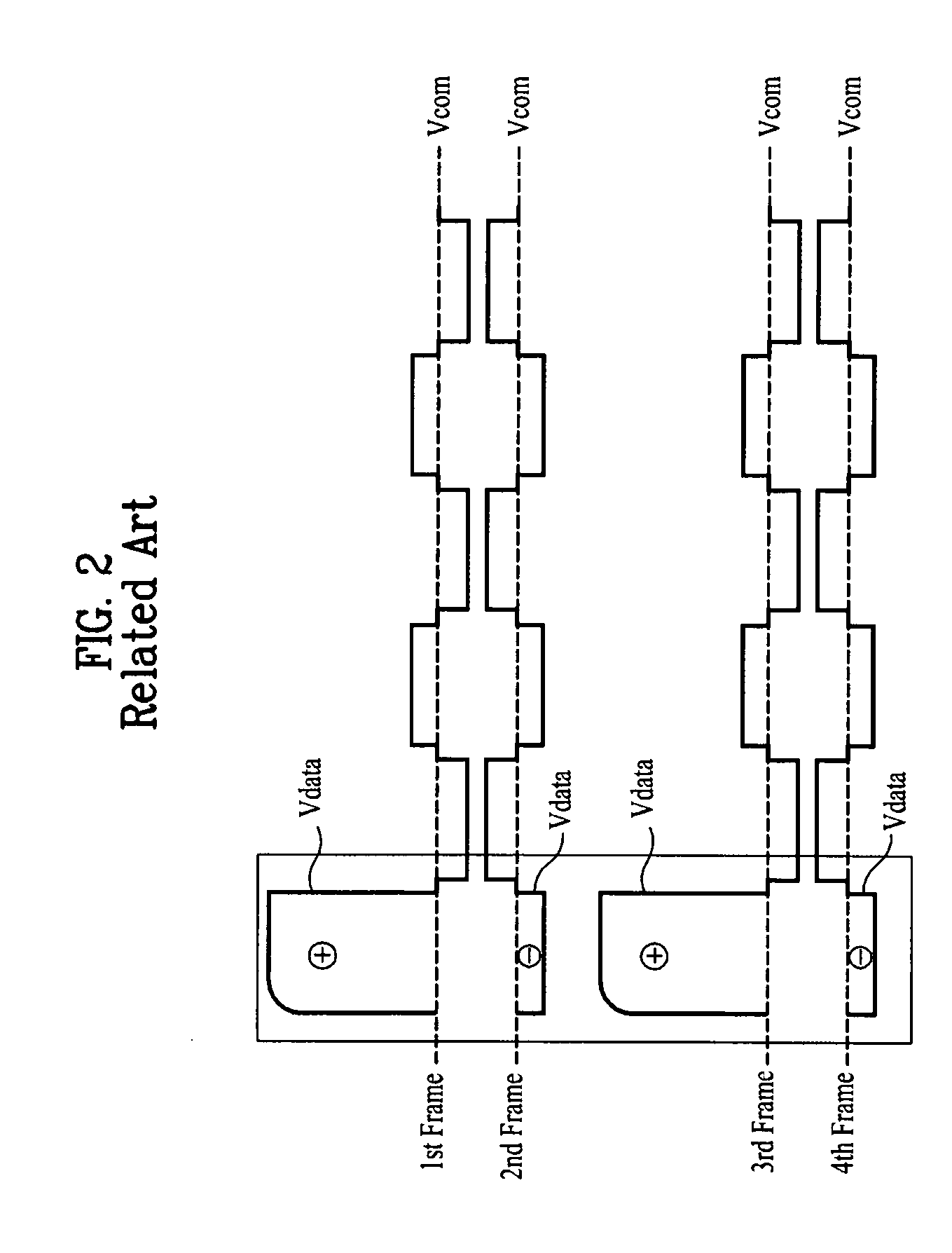
However, when any one of data voltages having opposite polarities is dominantly supplied for a prolonged period of time, image sticking may occur.
That is, DC image sticking occurs.
The moving image display quality of the LCD device may be degraded not only due to DC image sticking, but also due to flicker, namely, a periodic brightness difference visible to the naked eye of a viewer.

Method used


Image

  • Liquid crystal display device and driving method thereof
  • Liquid crystal display device and driving method thereof
  • Liquid crystal display device and driving method thereof

Examples


first embodiment

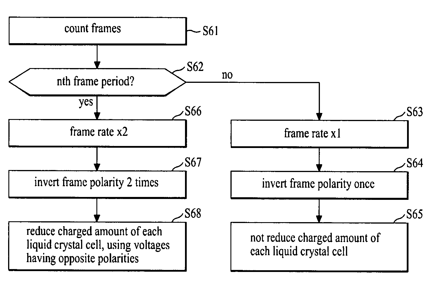
[0045]FIG. 5 is a view illustrating the polarities of voltages respectively charged in the same crystal cell in a plurality of frame periods in a liquid crystal display (LCD) device according to an exemplary embodiment of the present invention. FIG. 6 is a flow chart illustrating a method for driving the LCD device in accordance with the present invention.

[0046]Referring to FIGS. 5 and 6, in accordance with the LCD device driving method according to an illustrated embodiment of the present invention, a timing signal, which is input, together with digital video data, is counted, for counting of a frame period (S61).

[0047]In accordance with the LCD device driving method according to the illustrated embodiment of the present invention, a frame polarity inversion is executed at intervals of one frame period, to invert the polarity of a data voltage charged in liquid crystal cells Clc at intervals of one frame period. In accordance with the LCD device driving method, however, the frame r...

second embodiment

[0095]FIG. 17 is a flow chart for explaining a method for driving the LCD device in accordance with the present invention.

[0096]In the LCD device driving method according to the second embodiment of the present invention, as shown in FIG. 17, input data is first analyzed, to determine whether or not the input data corresponds to data having a possibility of DC image sticking, such as interlaced data or scrolled data, and the counting of a frame period is counted (S171 and S172).

[0097]In accordance with the second embodiment of the present invention, data of two neighboring lines is repeatedly compared, using a line memory and a comparator, to determine whether or not the difference in data between the two neighboring lines is equal to or higher than a predetermined critical value. When the data difference between the two neighboring lines is equal to or higher than the predetermined critical value, the input data may be determined to be interlaced data. In accordance with the second...


PUM


Abstract

A liquid crystal display (LCD) device and a method for driving the LCD device are disclosed. The LCD device includes a frame rate adjusting circuit for controlling a frame rate to be maintained at a 1-fold rate in frame periods other than an Nth frame period (“N” is a multiple of 8 or more), while being increased to an “i”-fold-accelerated rate (“i” is a positive integer of 2 or more) in the Nth frame period, to output reference timing signals in the frame periods other than the Nth frame period, and to output accelerated timing signals in the Nth frame period, a timing controller for generating data and gate timing control signals, based on at least one of each reference timing signal and each accelerated timing signal, and a logic circuit for accelerating a frequency of a polarity control signal in the Nth frame period.

Description

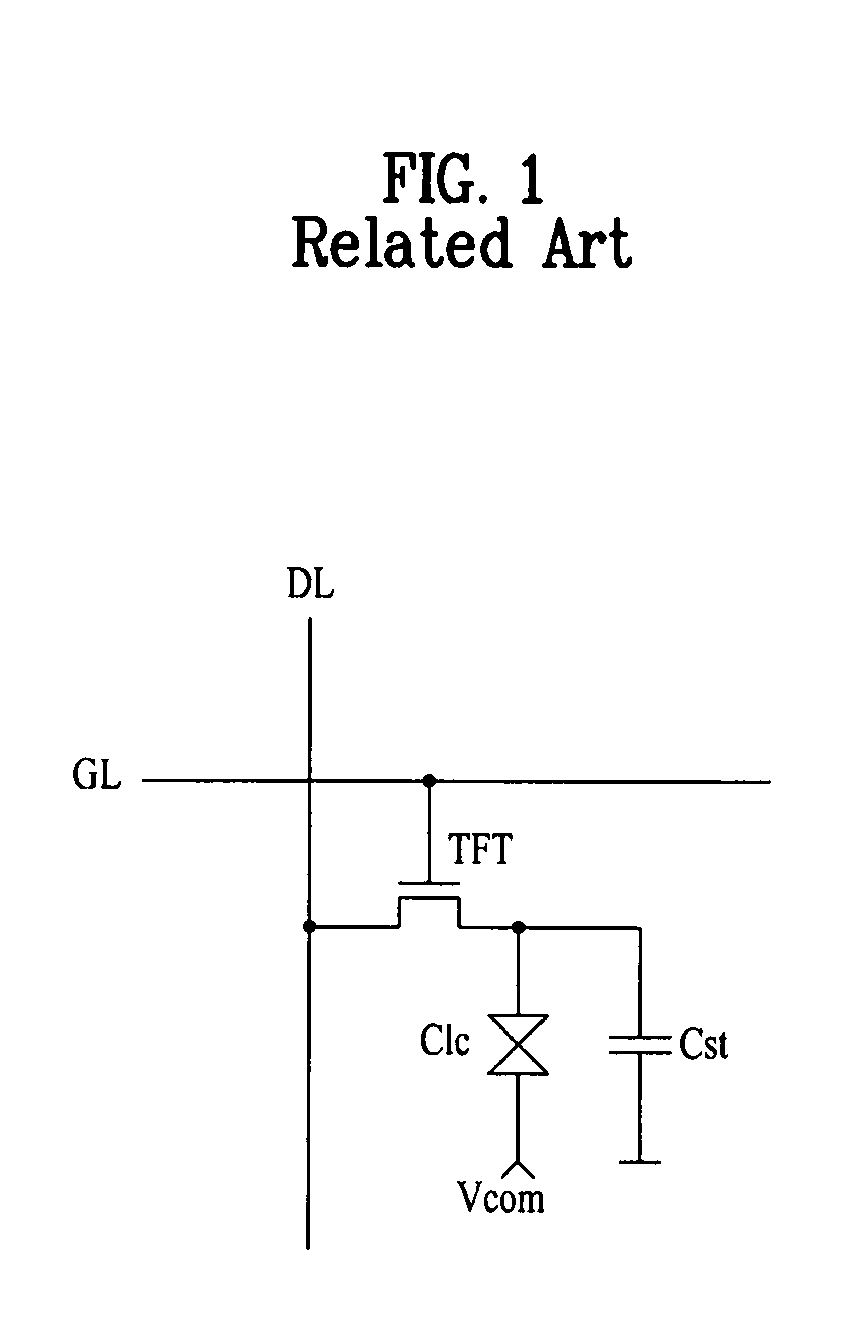
[0001]This application claims the benefit of the Korean Patent Application No. 10-2007-0046124, filed on May 11, 2007 which is hereby incorporated by reference for all purposes as if fully set forth herein.BACKGROUND OF THE INVENTION[0002]1. Field of the Invention[0003]The present invention relates display devices, and more particularly, to a liquid crystal display (LCD) device and a driving method thereof for reducing or eliminating direct current image sticking and flicker.[0004]2. Discussion of the Related Art[0005]LCD devices display an image by controlling the light transmittance of liquid crystal cells in accordance with a video signal. FIG. 1 illustrates a liquid crystal cell of an active matrix type LCD device. In such an active matrix type LCD device, data voltages, which are supplied to liquid crystal cells Clc, are switched by thin film transistors (TFTs) formed in respective liquid crystal cells Clc under the active control of data to achieve an enhancement in the displa...

Claims


Application Information

Patent Timeline
IPC IPC(8): G09G3/36
CPCG09G3/3614G09G3/3648G09G2340/16G09G2330/023G09G2340/0435G09G2320/0247G09G3/36G02F1/133G09G3/20
Inventor SONG, HONG SUNGMIN, WOONG KIJANG, SU HYUK
Owner LG DISPLAY CO LTD
Learn More