Elongated illuminators configuration for LCD displays

a technology of illuminators and liquid crystal displays, which is applied in the direction of fibre light guides, lighting and heating apparatus, instruments, etc., can solve the problems of insufficient image quality of lcd displays, less and less desirable conventional flat panel backlight solutions using side-mounted ccfls, and easy warping in manufacture, so as to reduce the cost and dimensional profile of backlight components.

Inactive Publication Date: 2008-11-20
SKC HAAS DISPLAY FILMS CO LTD
View PDF16 Cites 131 Cited by
  • Summary
  • Abstract
  • Description
  • Claims
  • Application Information

AI Technical Summary

Benefits of technology

[0021]It is an advantage of the present invention that it employs solid-state light sources to provide area backlighting for a display. The apparatus of the present invention is scalable and is particularly adaptable to larger sized LC panels.
[0022]It is a further advantage of the present invention that it eliminates the need for a light guide plate or other planar type panel, whi

Problems solved by technology

While liquid crystal displays (LCDs) offer a compact, lightweight alternative to cathode ray tube (CRT) monitors, there are many applications for which the image quality of LCD displays are not yet satisfactory, particularly as the relative size of these devices increases.
Conventional flat panel backlight solutions using side-mounted CCFLs are less and less desirable as display size increases and, particularly as display area grows, can be susceptible to warping in manufacture or due to heat.
Light-guiding backlight techniques that are conventionally employed for smaller devices are increasingly hampered by low brightness or luminance levels and by problems related to poor uniformity as the display size increases, such as would be needed for digital TV, for example.
Existing backlight apparatus for LCD displays and other display and illumination applications, often using banks of CCFLs lined up in parallel, can be relatively inefficient.
The CCFL light source itself presents an environmental problem for disposal, since these devices contain some amount of mercury.
As is well known, the spectral characteristics of CCFLs are relatively poor when compared to other types of light sources.
However, except for specialized uses such as for some types of instrument panels and for very high-end monitors and TV panels, array arrangements do not appear promising, due to problems of poor color and brightness uniformity, high parts count, high heat, and dimensional requirements.
However, although there have been a number of solutions proposed, there are significant drawbacks inherent to each type of solution, particularly when faced with the problem of backlighting for a display panel of standard laptop dimensions or larger.
The 2-D matrix proposed in the '921 Deloy et al. disclosure would be difficult to implement inexpensively, of relatively high cost, bulky, and prone to uniformity problems.
The molded panel arrangement described in the '224 DuNah et al.

Method used


Image

  • Elongated illuminators configuration for LCD displays
  • Elongated illuminators configuration for LCD displays
  • Elongated illuminators configuration for LCD displays

Examples


embodiment 1

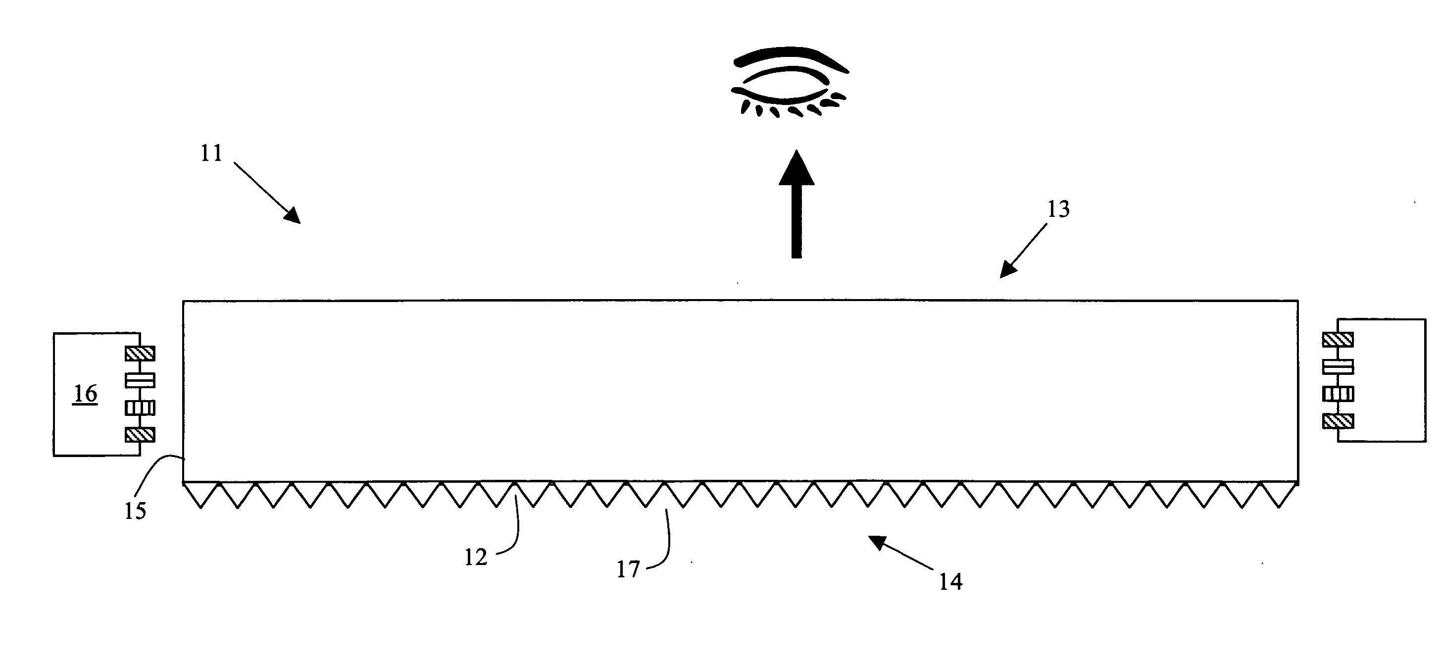
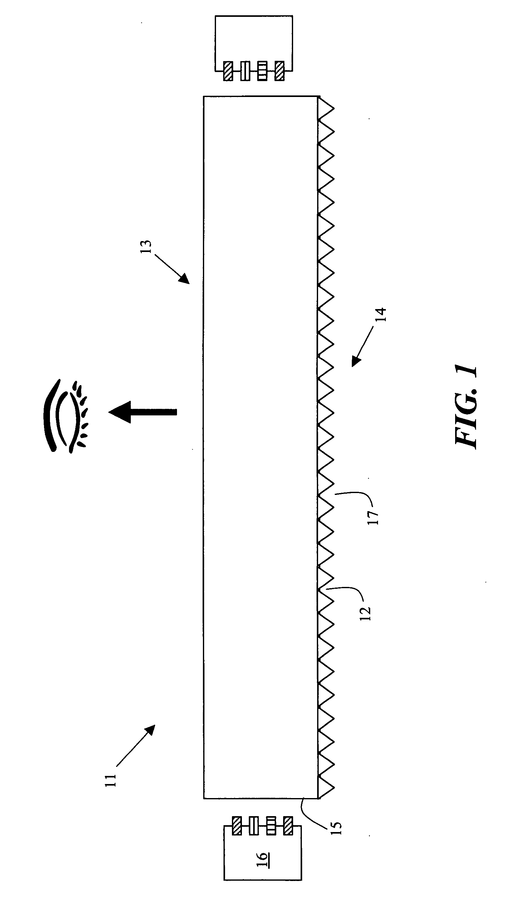
[0152]FIG. 1 is a side view of a elongated illuminator 11 with bottom prism-like structure on the non-view side, a view side 13 and a non-view side 14 (side opposite the view side). The light bar also has at least one light input ends 15 and at least one solid state light source 16. The prism-like structure 12 may have an included angled features of either constant angle of variable angle to control the amount and relative direction of light. Furthermore the prism-like structure may vary in feature density (shape, size and angle) as a function of the distance from light entering side. While depicted as having two light input side, it may have only one with a optional reflector on the opposite side. It should be noted that other embodiments of this invention may further comprise other light control elements on either the non-view side 14 as well as the view side 13. The functional aspects may include but are not limited to reflection both diffuse and specular, light shaping including...

embodiment 2

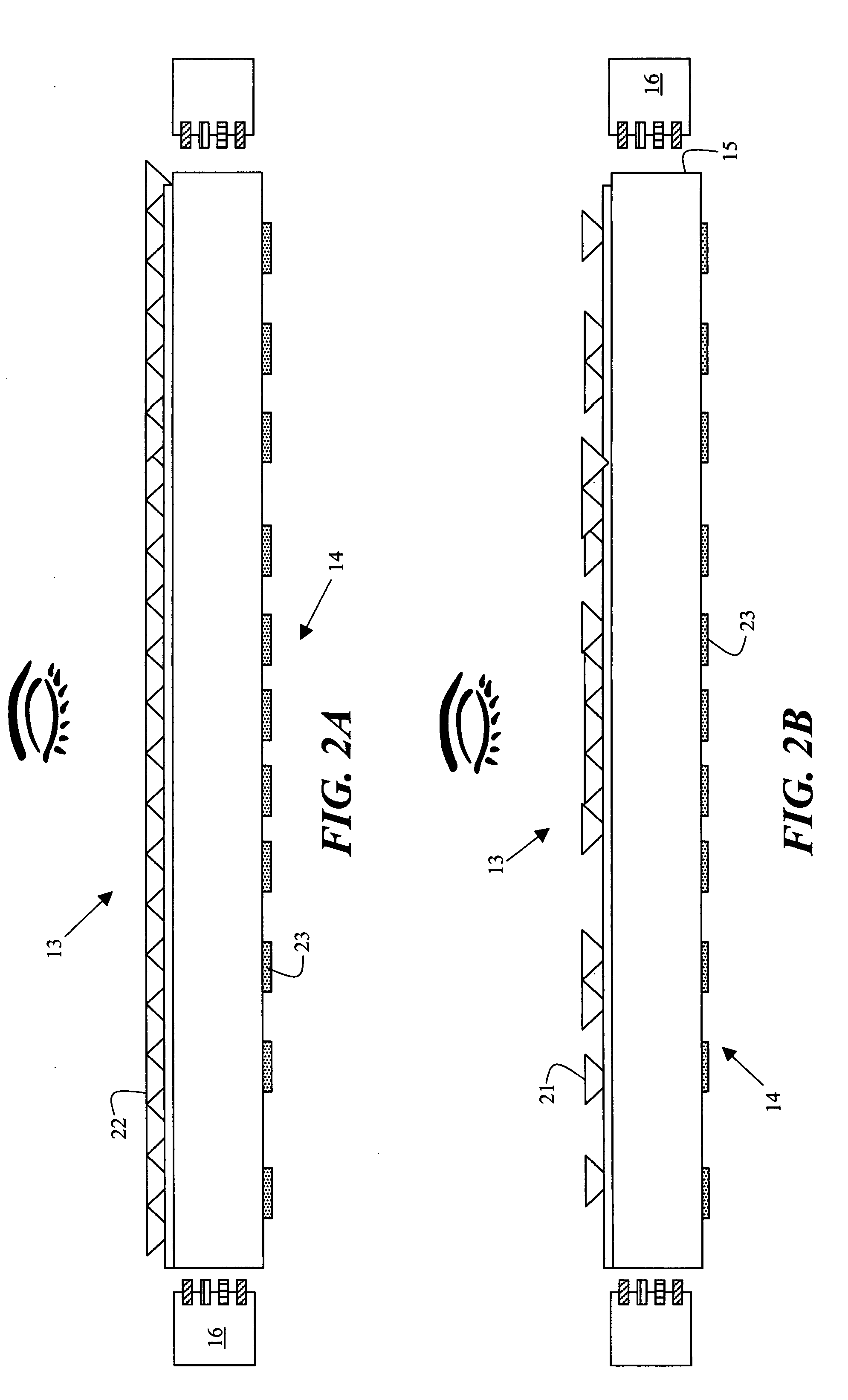
[0153]FIG. 2 is a further variation of the previous figure. FIG. 2A is a elongated illuminator with a view side 13 and a non-view side 14. There is a view side surface extraction feature 22 that is continuous in its pitch between extraction features and on the non-view side is a surface pattern (for example dots or other shape) that varies in their size and or density (relative dot area vs. non-dot area). The dot pattern may be printed or otherwise deposited or formed on the surface. The non-view side may vary in its relative size, density and reflectivity as a function from solid sate light source 16. In order to provide uniform light extraction, the density of the non-view side dots increases towards the center of the elongated illuminator. While this and other embodiments are described as having a view side, it should be noted that in many display applications, this side of the light bar may not be viewed directly as there may be one or more intervening layers, films, other featu...

embodiment 3a and 3b

[0155]FIG. 3A is another embodiment of this invention in which an integral elongated illuminator pattern is formed by removing portions of the material from a lightguide plate. The integral elongated illuminator could also be molded. The interconnected pattern provides additional stiffness to the elongated illuminators as well as an additional pathway for light move between elongated illuminator-like segments. Both a top view and perspective view for embodiment shown in 3A. There are solid state light source 16 and an air gap 32 that forms a region of low refractive index that aids in the TIR (total internal reflection) of light from the light source within solid elongated illuminator section 34. This elongated illuminator may also have a reflector on the opposite end of the light source in those embodiments in which the light source is provided from one end. Such an arrangement provides for the returns of light into the elongated illuminator for extraction towards the view side. Al...


PUM


Abstract

A solid waveguide comprises opposite TIR surfaces further comprising:
a) at least one light input surface for coupling light from a solid state light source;
b) at least one mixing section;
c) at least one light emitting surface; and
d) a desired pattern of light redirecting features located on one TIR surface or between the TIR surfaces.

Description

FIELD OF THE INVENTION[0001]This invention relates to the art of backlight apparatus for a display and a liquid crystal display employing such apparatus. In particular, the present invention relates to a Liquid Crystal Display (LCD) backlight with solid-state light sources.BACKGROUND OF THE INVENTION[0002]While liquid crystal displays (LCDs) offer a compact, lightweight alternative to cathode ray tube (CRT) monitors, there are many applications for which the image quality of LCD displays are not yet satisfactory, particularly as the relative size of these devices increases. Larger LCD panels, such as those used in laptop computer or larger displays, are transmissive, and thus require a backlight. This type of light-providing surface, positioned behind the LCD panel, directs light outwards and towards the LCD.[0003]Conventional approaches for backlighting use various arrangements of cold cathode fluorescent (CCFL) light sources with light guide plates, one or more types of enhancemen...

Claims


Application Information

Patent Timeline
IPC IPC(8): F21V7/04
CPCG02B6/001G02B6/002G02B6/0021G02B6/0038G02B6/0043G02B6/0046G02B6/0053G02B6/0055G02B6/0068G02B6/0078G02B6/00G02F1/1335
Inventor AYLWARD, PETER T.BOURDELAIS, ROBERT P.HONG, QIPALMERI, JOHN M.GATES, LEONARD S.
Owner SKC HAAS DISPLAY FILMS CO LTD
Why Eureka
Try Eureka