
Call Release in Communication Networks

a communication network and call technology, applied in the field of call release in communication networks, can solve the problems of data consistency, no longer automatic response, and subsequent respons

Inactive Publication Date: 2008-11-20
NOKIA SIEMENS NETWORKS GMBH & CO KG
View PDF0 Cites 12 Cited by
  • Summary
  • Abstract
  • Description
  • Claims
  • Application Information

AI Technical Summary

Benefits of technology

[0054]Owing to the notification to at least one network node along the connection, the logical coupling between the two layers, which are implemented on a distributed basis, is strengthened, as a result of which the inconsistencies described (bearer no longer available—charge metering continues) can be more easily avoided.
[0055]Owing to the notification on the resource control layer, the scaling problem is significantly mitigated because the signaling messages to these network nodes can be dispensed with.
[0056]The problem of the time offset in the case of a high-level recovery of a controller is alleviated since the notification on the resource control layer can be effected in immediate proximity in time to the release of the connection, without any need to wait for an activation of corresponding protocols of the call control layer. Moreover, the notifications can be generated in parallel by the processors on the modules if different modules are affected by the control messages. This is more effective than the generally forcibly sequentialized sending of signaling messages by a centralized controller.
[0057]In the event of a high-level recovery of a media gateway controller from which an interconnection with a TDM network is effected, a notification to an adjacent TDM switching node (e.g. due to failure or reentry into service of PCM links) leads on the TDM side to ISUP synchronization messages (GRS / RSC) from the TDM switching node to the controller undergoing the recovery, which messages, if not answered, are repeated cyclically. The controller undergoing the recovery begins, from a certain point in its recovery, to send GRS / RSC messages itself and to acknowledge those received. Because adjacent TDM switching nodes also assist in taking on the work of ISUP synchronization following recovery of the controller, on the one hand the controller undergoing recovery is dynamically relieved of its load, and on the other the synchronization is completed more rapidly, the full call processing availability of the controller thereby being restored at an earlier point in time.
[0059]In the event of notification due to failure (e.g. deactivation) of a transmission channel to a switching node of a circuit-switched network, the failure—provided it lasts long enough (e.g. several seconds)—is detected by the hardware monitoring of the node. This node thereupon initiates the release of the TDM bearer on both sides in the circuit-switched network. If the charging is handled in this network (e.g. if the node is disposed in an ingress-side circuit-switched network to which the subscriber to be charged is also assigned), this charging is also stopped. The failure of the transmission channel advantageously affects no connections that were not to be released if (as is the case, for example, for a high-level recovery of the controller) all the connections in the assigned gateways are released. As a result of the tried-and-tested release mechanisms existing in the circuit-switched network, this termination of the charging takes place close in time to the interruption of the end-to-end bearer in the media gateway. In the event of a high-level recovery of a media gateway controller, in this way the charge metering is stopped close in time to the failure of the bearer and is not delayed by the recovery.
[0062]Provided this relayed notification is communicated, not by failure of the transmission channel, but by means of a message to the assigned controller and then on the call control layer, there are advantageously no interruptions to other connections that are also carried in the transmission channels to the circuit-switched network. In this way, in addition, a return is made as quickly as possible to the architecture-compliant signaling on the call control layer. Furthermore this return is performed in a distributed manner to a plurality of controllers which for their part are not undergoing a recovery, so a very efficient distribution of the signaling load is effected, which load, with architecture-compliant signaling, would otherwise have to be borne on its own by the controller, which, apart from the absence of load distribution, in any case also has insufficient resources available during its recovery to be able to process this signaling.

Problems solved by technology

In a network in which there is no clear decoupling of these two layers, an error of said kind usually leads automatically to a consequent response on the resource control layer (e.g. to the failure of a transmission link) as a result of the integrated hardware platform.
In the case of (physical) distribution of the two layers, however, this consequent response no longer occurs automatically.
If the coupling of the two layers is too slight, there are problems with data consistency (e.g. a false image of the states in the resource control layer is present in the call control layer; charging continues in spite of bearer failure).
If the coupling is too strong (e.g. a failure of an entity of the call control layer also leads to an equivalent failure of the associated entities of the resource control layer), then there are unnecessarily long downtimes and unnecessary risks during the restart of the network.
This can, however, lead to problems with the charging of the call, because the (bearer) connection can no longer be used for an end-to-end transmission of information between subscribers already after the first control command if the media gateway affected by said command no longer recognizes the call cleared in said way and no longer discharges the gateway function.

Method used


Image

  • Call Release in Communication Networks
  • Call Release in Communication Networks
  • Call Release in Communication Networks

Examples


Embodiment Construction

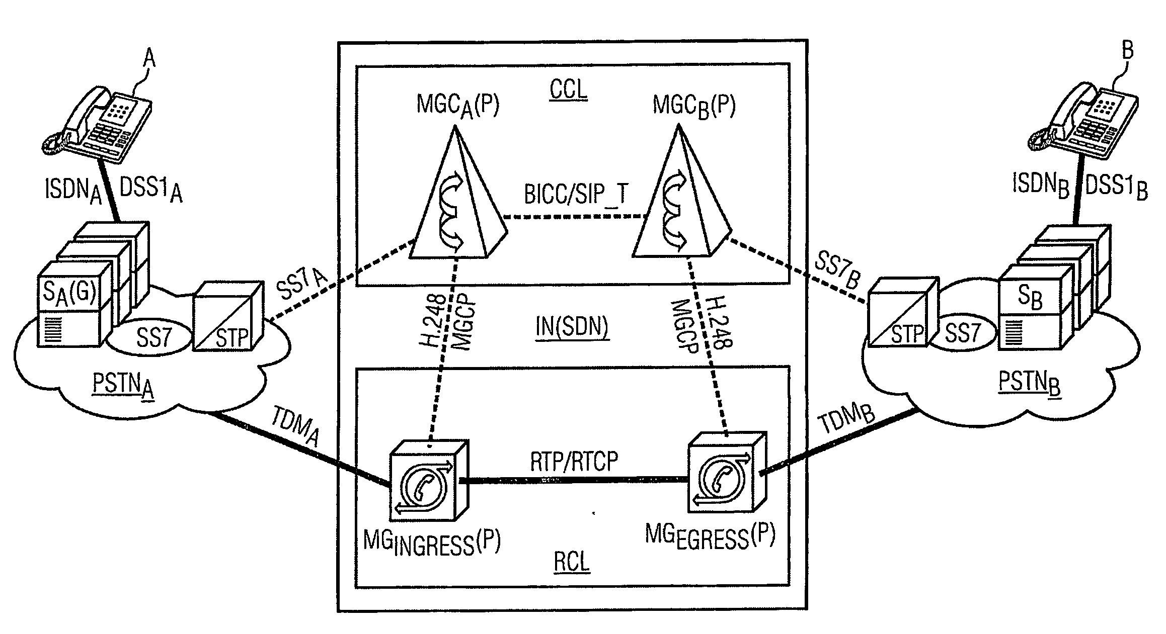
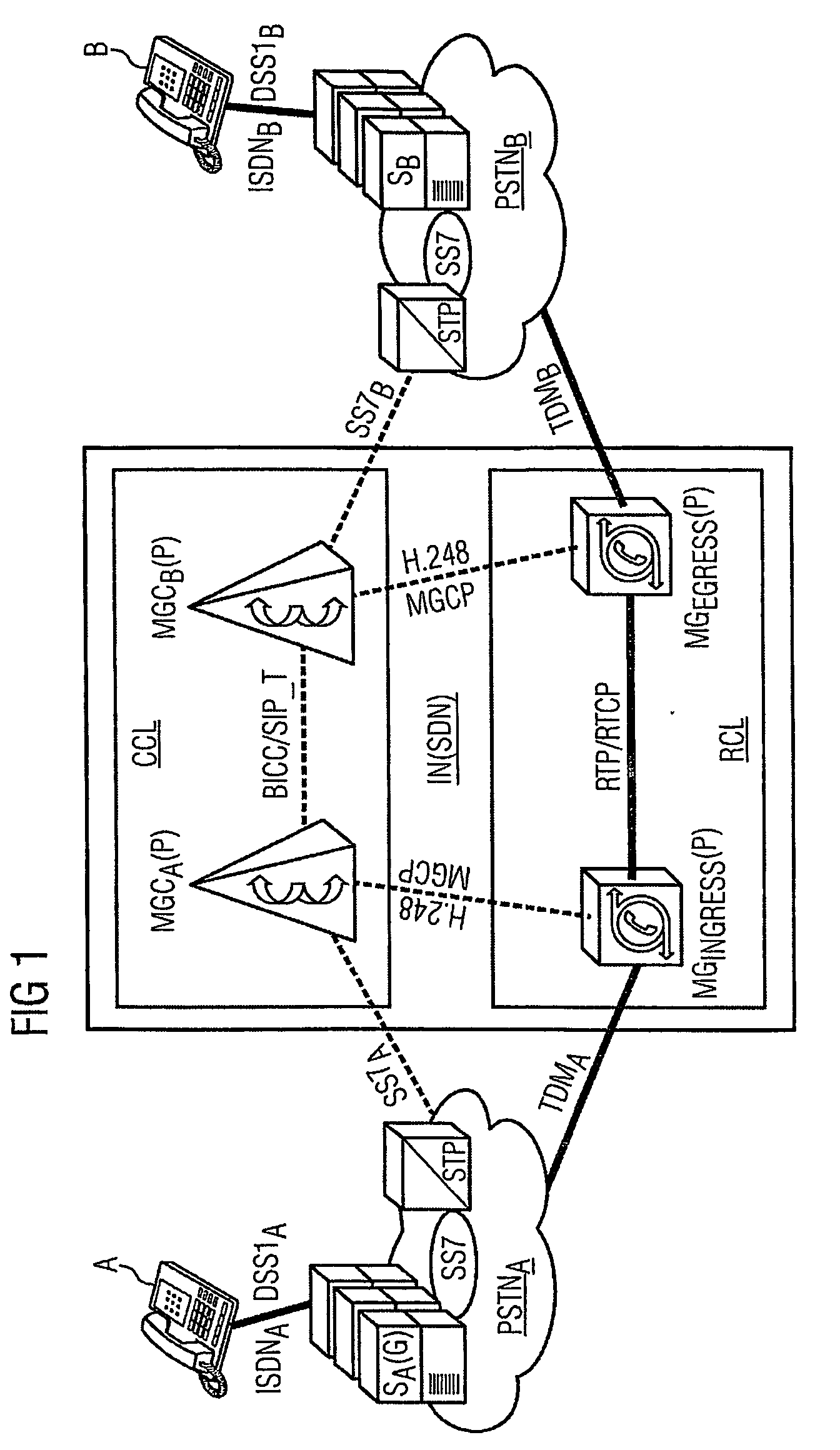
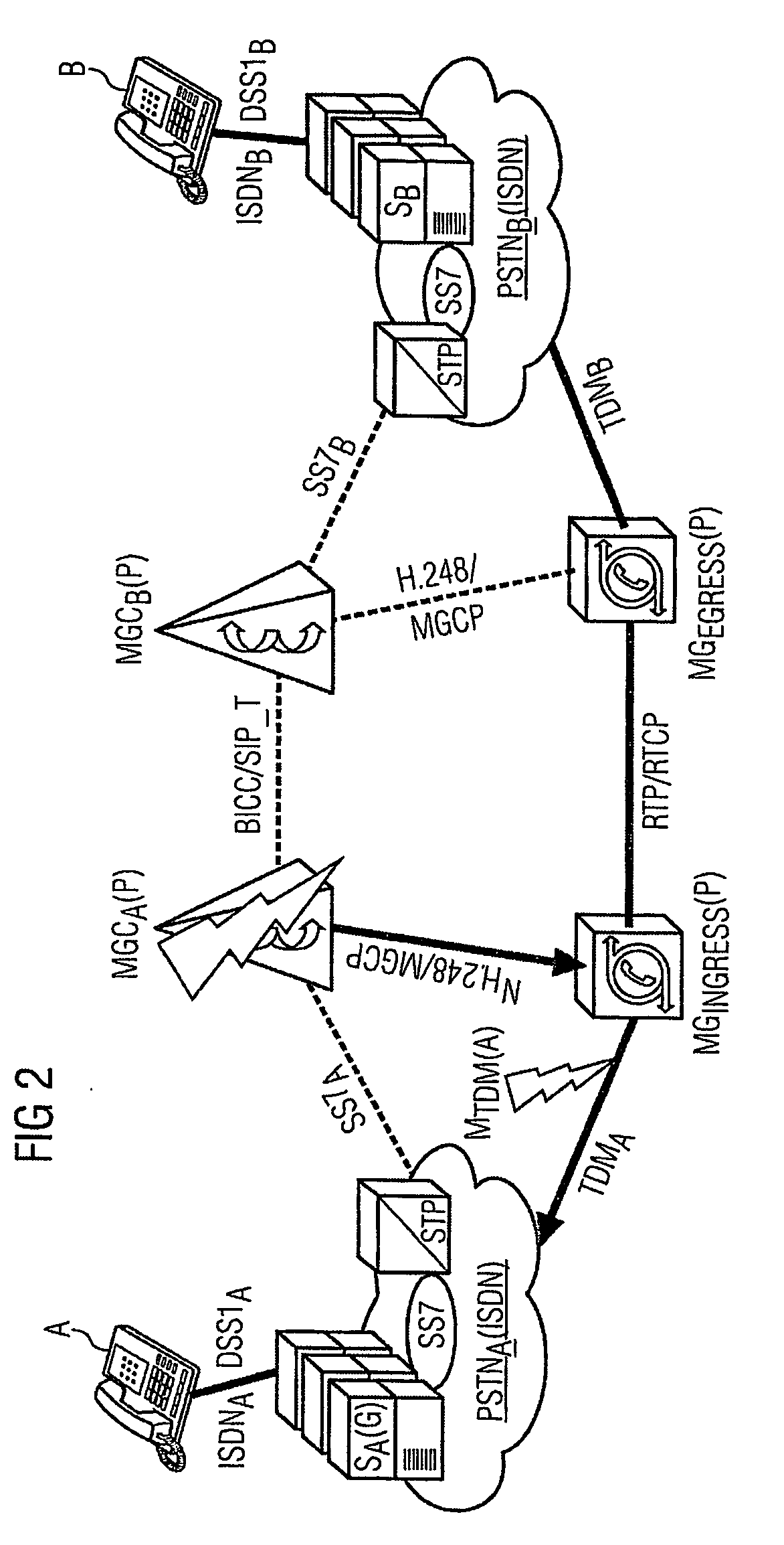
[0067]FIG. 1 shows an exemplary arrangement for performing the method according to the invention. It comprises two circuit-switched networks PSTNA, PSTNB and a communication network IN which is preferably embodied as an integrated voice-data network SDN. The three networks are interconnected to form a hybrid network in which the network IN in particular is used for virtual trunking of voice connections between the PSTN networks. The network IN is preferably embodied as an IP network (e.g. the internet). For the appropriate person skilled in the art it is obvious here that the invention can of course be used in other network scenarios, in particular further packet-oriented networks, such as, for example, an intranet, extranet, a local area network (LAN) or a corporate network embodied, for example, as a virtual private network (VPN).

[0068]The network IN includes a call control layer CCL, to which the controllers MGC are assigned, and a resource control layer RCL, to which the media g...


PUM


Abstract

A controller requests a gateway to release a call. The gateway then disconnects and communicates the disconnect to at least one additional network node along the end-to-end connection on the resource control level. In the case of a high level recovery of a controller a temporally close stop of charging of disconnected connections is effected without the controller signaling it.

Description

CROSS REFERENCE TO RELATED APPLICATIONS[0001]This application is the US National Stage of International Application No. PCT / EP2004 / 050700, filed May 4, 2004 and claims the benefit thereof. The International Application claims the benefits of European Patent application No. 10338055.8 DE filed Aug. 19, 2003, all of the applications are incorporated by reference herein in their entirety.FIELD OF THE INVENTION[0002]In the past, two important types of communication network for transferring information have developed: packet-oriented (data) networks and circuit-switched (voice) networks. The convergence of these two network types has led to the development of convergent (voice-data) networks. The merger of these different network types has resulted in hybrid networks, in which the subject matter of the present invention is utilized with particularly noteworthy advantages.BACKGROUND OF THE INVENTION[0003]Circuit-switched networks—also called voice networks or telephone networks—are design...

Claims


Application Information

Patent Timeline
IPC IPC(8): H04L12/26H04L12/66H04M7/00H04Q3/00
CPCH04M7/1245H04Q3/0025H04Q2213/13034H04Q2213/13106H04Q2213/13109H04Q2213/1313H04Q2213/13167H04Q2213/13176H04Q2213/13196H04Q2213/13271H04Q2213/13389
Inventor TEGELER, JURGEN
Owner NOKIA SIEMENS NETWORKS GMBH & CO KG
Learn More