
Air convection warmer with noise reduction filter

a technology of noise reduction filter and air convection warmer, which is applied in the direction of machines/engines, contraceptives, liquid fuel engines, etc., can solve the problems of substantial noise, high noise of air convective warmers, and annoyance of patients by substantial noise, so as to reduce noise

Inactive Publication Date: 2008-11-20
SMITHS MEDICAL ASD INC
View PDF10 Cites 8 Cited by
  • Summary
  • Abstract
  • Description
  • Claims
  • Application Information

AI Technical Summary

Benefits of technology

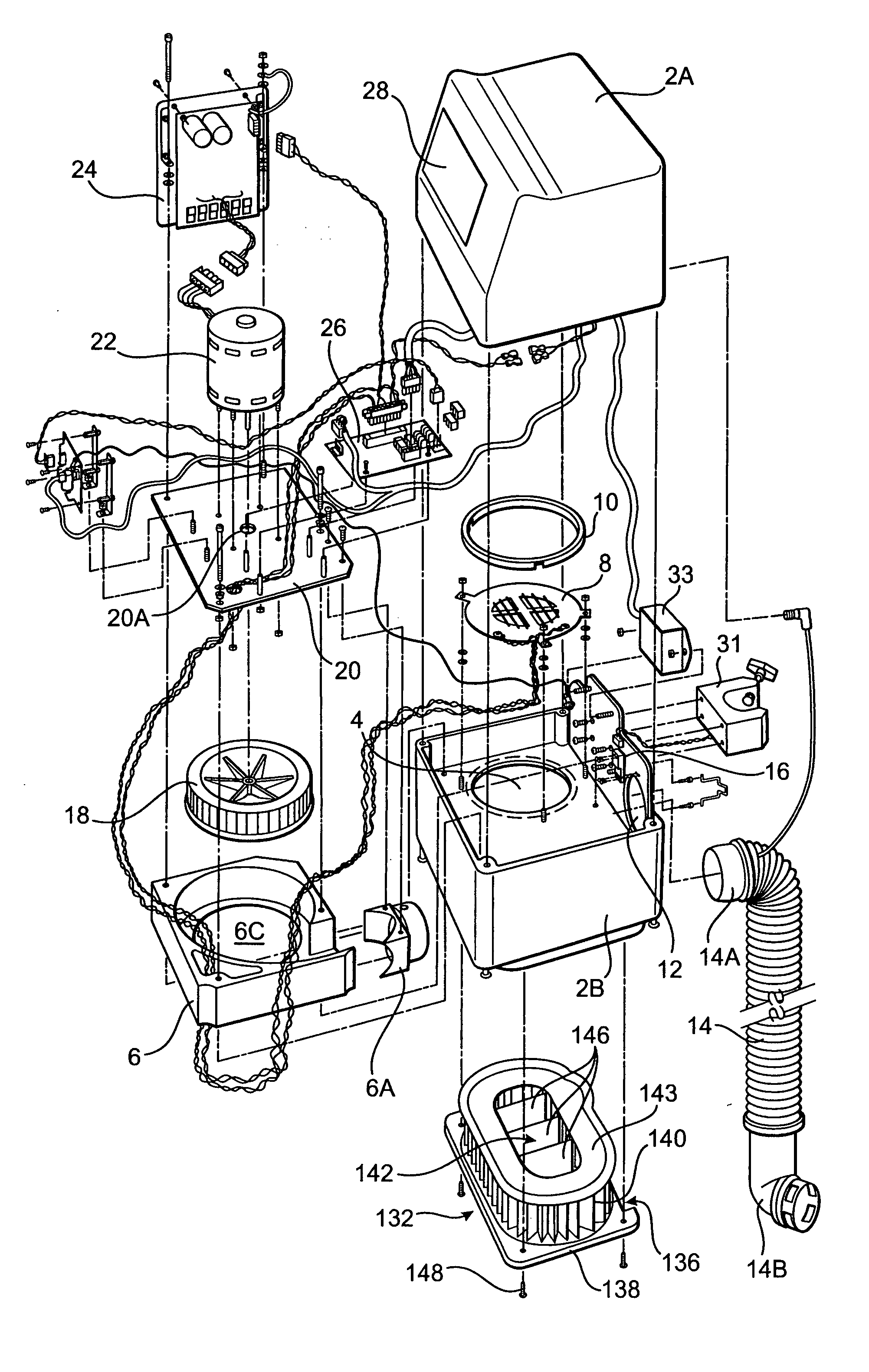
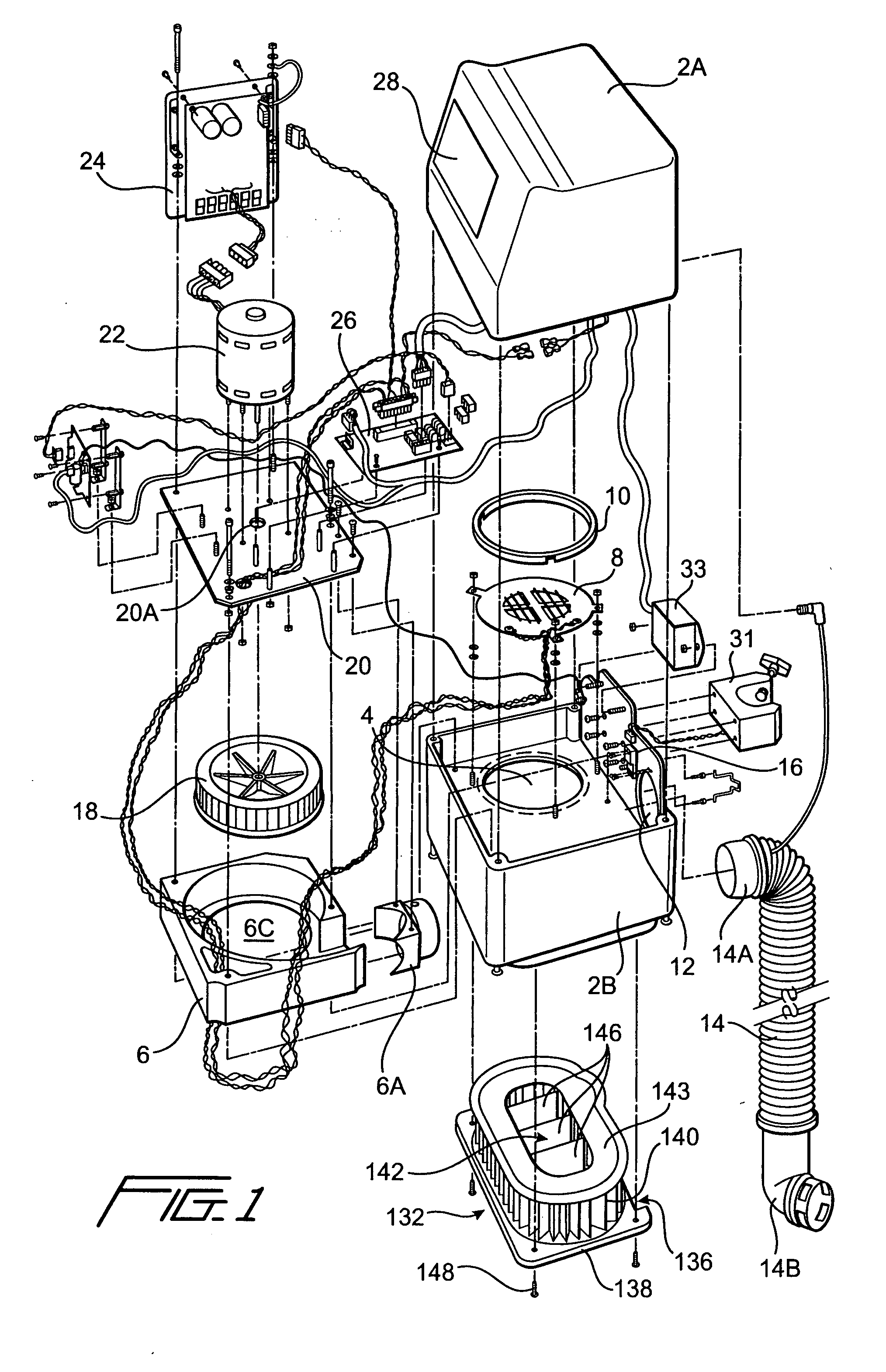
[0006]The air convective warmer of the instant invention is an improvement of the existing EQUATOR® air warmer manufactured by the assignee of the instant application. Instead of reconfiguring the construction of the air warmer, the inventors found that by disrupting the air flow pattern in the air filter, the noise of the machine which presumably results from the blower and the air stream passing through the housing of the warmer, could be substantially reduced. Thus, instead of having to modify the whole machine, only the air filter of the air convective warmer needs to be reconfigured, thereby enabling the manufacturing of an airwarmer with a reduced noise level. So, too, the noise level of air warmers that are already in service can be readily reduced by simply retrofitting those warmers with the inventive air filter.
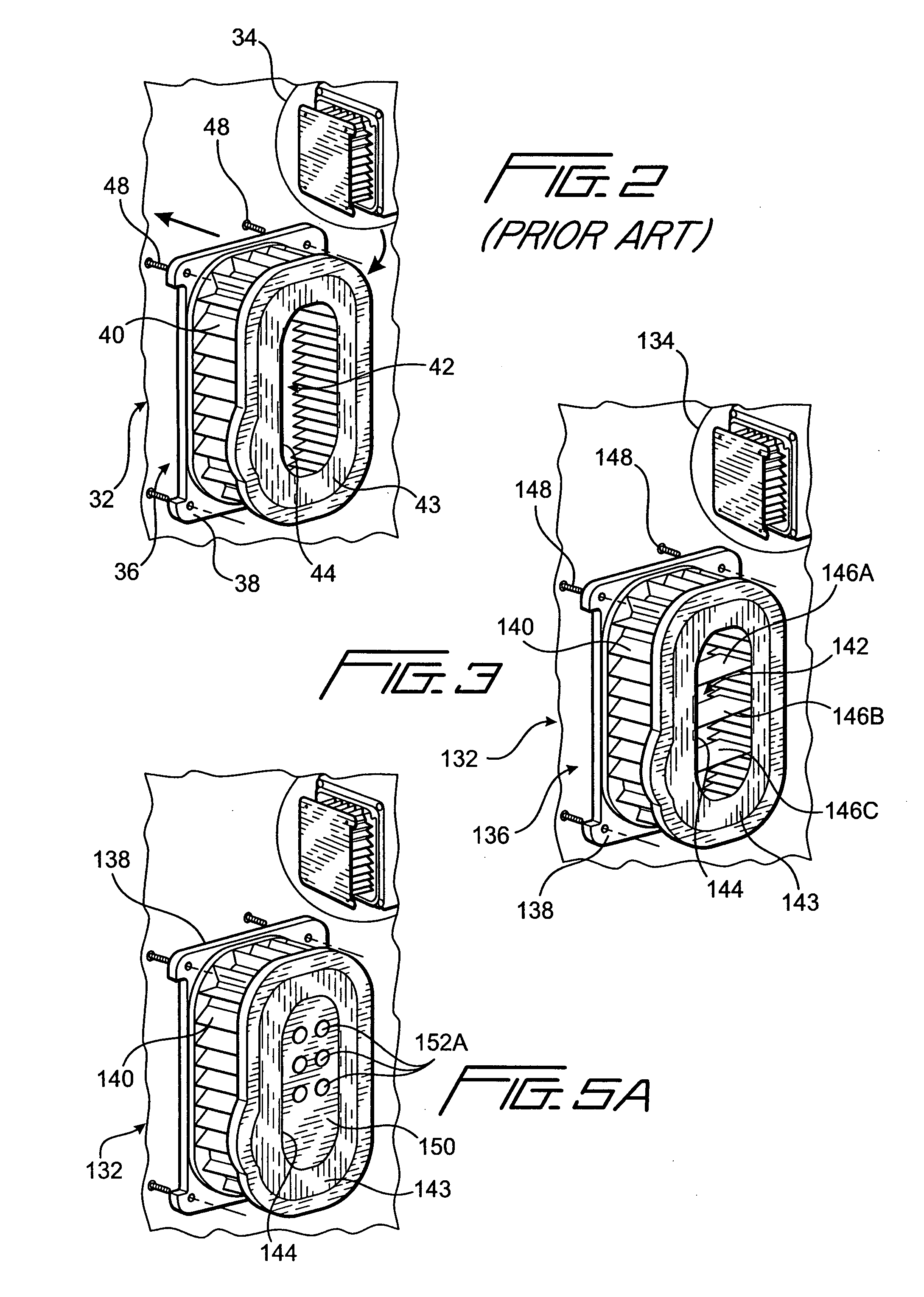
[0010]A second embodiment for interrupting the flow of air in the filter is by means of sealing the top opening of the filter, and extending through the sealed cover at least one open ended tube into the interior of the filter. The end of the tube that is extended into the filter is spatially separated from the base of the filter so that air may pass from the interior of the filter to the air plenum of the warmer through the open-ended tube. By providing a plurality of open-ended tubes, it was found that the air flow in the interior of the filter is disrupted in such a way that the noise level generated by the warmer is substantially reduced, and yet at the same time, the strength of the air stream flow from the warmer is not reduced, so that the efficiency with which the air warmer inflates the convective blanket connected thereto is not affected.
[0011]The air flow from the filter may also be interrupted by the covering of a portion of the filtering material by an air impermeable material, for example, a piece of plastic, so that the air input to the interior of the air filter passes into the air filter from only one portion of the filtering material. Further, for the air filter with the partition(s), the air flow is interrupted by having to go around the air filter between the partitions and the filter material and through the filter material into the interior of the filter. The inventors found that to be optimum, approximately ¼ to ¾, and preferably approximately 55%, of the filtering material be covered by the air impermeable material to both reduce the noise level and to continue to maintain the effectiveness of the air output from the air warmer.
[0012]The instant invention therefore relates to an apparatus for outputting temperature regulated air to an inflatable blanket at a reduced noise level that comprises a housing having an air inlet and an air outlet, an air conditioning unit, a blower for directing air from the air inlet to the air conditioning unit and from there to the air outlet to inflate the blanket, and an air filter interposed between the air inlet and the air outlet to filter the air from the air inlet, with the air filter having fitted thereto air intercept mechanism for interrupting the flow of air traversing through the air filter to the blower to thereby reduce the noise generated by the flow of forced air in the housing and attributable to at least the air blower.
[0015]The instant invention also relates to the method of reducing noise in an air convective warmer that has a housing having an air inlet and an air outlet, a blower to direct the air input from the air inlet to the air outlet, and an air conditioning unit to treat the air input from the air inlet so that temperature regulated air is output from the air outlet to inflate a convective blanket connected thereto. The method in particular recites the step (a) of positioning an air filter in the housing between the air inlet and the air outlet so that air from the air inlet passes through the air filter, and the step (b) of fitting to the air filter an air intercept mechanism for disrupting the flow of air in the air filter being routed to the air conditioning unit and the blower.

Problems solved by technology

Most, if not all, air convective warmers produce a high level of noise, at least for some of the patients and others who may be close to the machine.
The noise from the blower, along with the air stream flow through the convective warmer, tend to produce substantial noise.
Such substantial noise could be an annoyance to the patient.

Method used


Image

  • Air convection warmer with noise reduction filter
  • Air convection warmer with noise reduction filter
  • Air convection warmer with noise reduction filter

Examples


first embodiment

[0028]The inventors have discovered that by disrupting the air flow in interior 42 of air filter 32, the noise level generated by the air convective warmer may be substantially reduced. To achieve this disruption of air flow, a modified air filter to be used the in the air convective warmer of FIG. 1 is shown in FIG. 3. As shown, air filter 132, like the air filter of FIG. 2, has a base 138 to which a filtering material 140 extends circumferentially to form an enclosed cavity 142 wherein ambient air passes from air inlet 136 through filtering material 140. An opening 144 is provided at air filter 132 for the filtered air in cavity 142 to be routed to housing 2b, and more specifically the cavity of air plenum 6, as indicated by its opening 6c. The filter material 140 is held in place by glue or other adhesive to base 138, and a top rim or cover 143 is attached to or covers the top of the filtering material to form the opening 144.

[0029]The inventors have found that by fitting the air...

second embodiment

[0031]the noise reduction air filter of the instant invention is shown in FIGS. 5a and 5b. The same components for the FIG. 5 embodiment as those shown in the FIG. 3 embodiment are labeled the same. As shown, the opening of air filter 132, which is formed by rim 143, is sealed by a cover 150. The interior cavity 142 of air filter 132, as best shown in FIG. 5b, is thereby enclosed, except for channels that are created by a plurality of open-ended tubes 152. Respective first open ends of tubes 152 are attached to cover 150 to thereby provide openings or apertures 152a to the opening 4 of housing 2b and also therefore the internal cavity 6c of air plenum 6. The other respective open ends of tubes 152, designated 152b in FIG. 5b, are spatially separated from base 138 by a predetermined distance 154, so that the filtered air in cavity 142 of air filter 132 passes through open ends 152b of the open-ended tubes 152 and from there passes into cavity 6c of air plenum 6 by way of openings 152...


PUM


Abstract

To reduce the noise level of air convective warmer, the air filter of the warmer is fitted with an air intercept mechanism to disrupt the flow of air that traverses inside the interior cavity of the air filter. By thus disrupting the air flow, the noise that otherwise would have been generated due to a non-interrupted air stream flow is lowered. The air intercept mechanism may be in the form of at least one partition positioned inside the interior cavity of the air filter. Alternatively, double-ended open tubes may be used, so long as the interior cavity of the filter is sealed, with only the tubes providing the passages for air to output from the air filter. Yet a third embodiment of the air reduction filter has an air impermeable material covering at least one portion of the surface area of the filtering material to prevent the inflow air from directly entering into the interior cavity of the air filter through the covered surface area.

Description

FIELD OF THE INVENTION [0001]The instant invention relates to air convection warmers and more particularly to an air convection warmer that operates at a lower noise level and yet produces the same throughput of temperature regulated air to inflate a convective blanket.BACKGROUND OF THE INVENTION [0002]To regulate the body temperature of a patient so as to prevent hypothermia in the patient, a convective blanket that provides a constant stream of warmed air to the patient is used. Convective blankets are inflated by air convective warmers. Most, if not all, air convective warmers produce a high level of noise, at least for some of the patients and others who may be close to the machine. This is because blowers are utilized in the convective warmers to propel a stream of air, heated or otherwise, from an air inlet to an air outlet, in order to inflate the convective blanket. The noise from the blower, along with the air stream flow through the convective warmer, tend to produce subst...

Claims


Application Information

Patent Timeline
Patent Type & Authority Applications(United States)
IPC IPC(8): F01D25/04
CPCA61F7/0097F04D29/663
Inventor PIERRE, JOSEPHSTARR, RACHELROOME, DAVID G.
Owner SMITHS MEDICAL ASD INC
Learn More