Flexible Circuit Electrode Array

Active Publication Date: 2008-11-20
CORTIGENT INC
View PDF13 Cites 91 Cited by
  • Summary
  • Abstract
  • Description
  • Claims
  • Application Information

AI Technical Summary

Benefits of technology

[0014]One aspect of the disclosure is a flexible circuit electrode array with more than one layer of metal traces comprising: a polymer base layer; more than one layer of metal traces, separated b

Problems solved by technology

While some of these early attempts met with some limited success, these early prosthetic devices we

Method used


Image

  • Flexible Circuit Electrode Array
  • Flexible Circuit Electrode Array
  • Flexible Circuit Electrode Array

Examples


Embodiment Construction

[0091]The following description is of the best mode presently contemplated for carrying out the invention. This description is not to be taken in a limiting sense, but is made merely for the purpose of describing the general principles of the invention. The scope of the invention should be determined with reference to the claims.

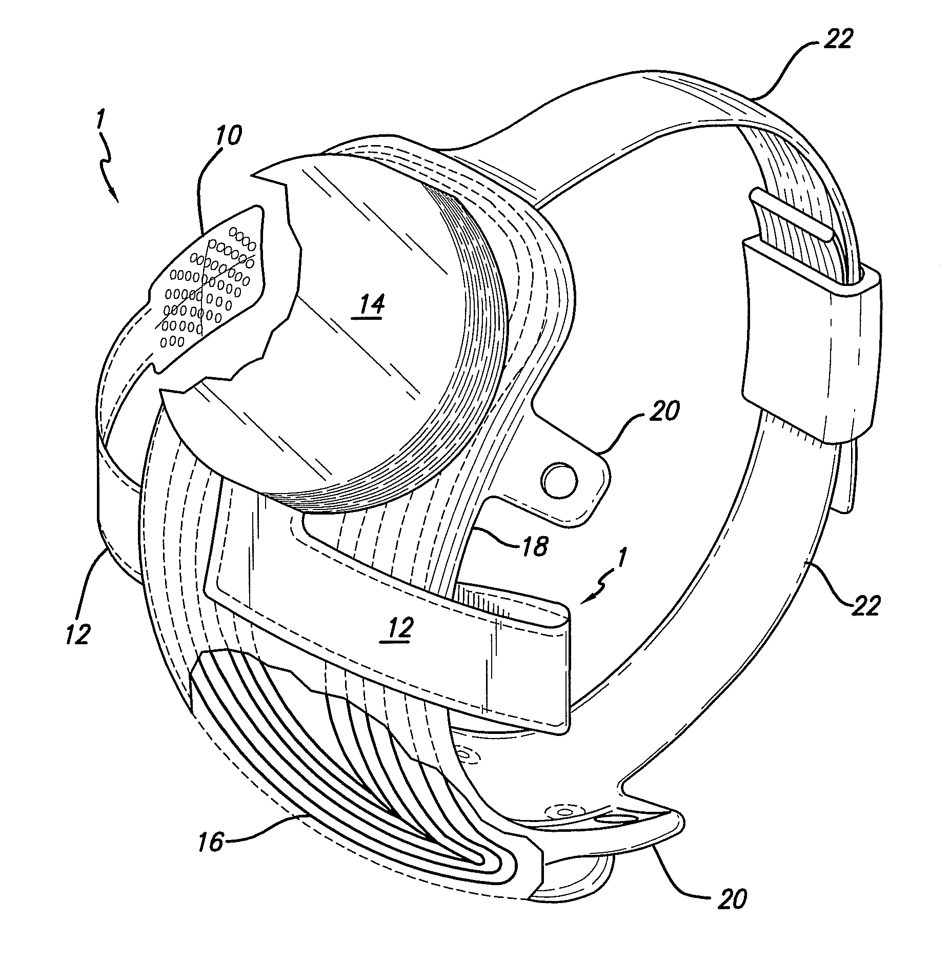
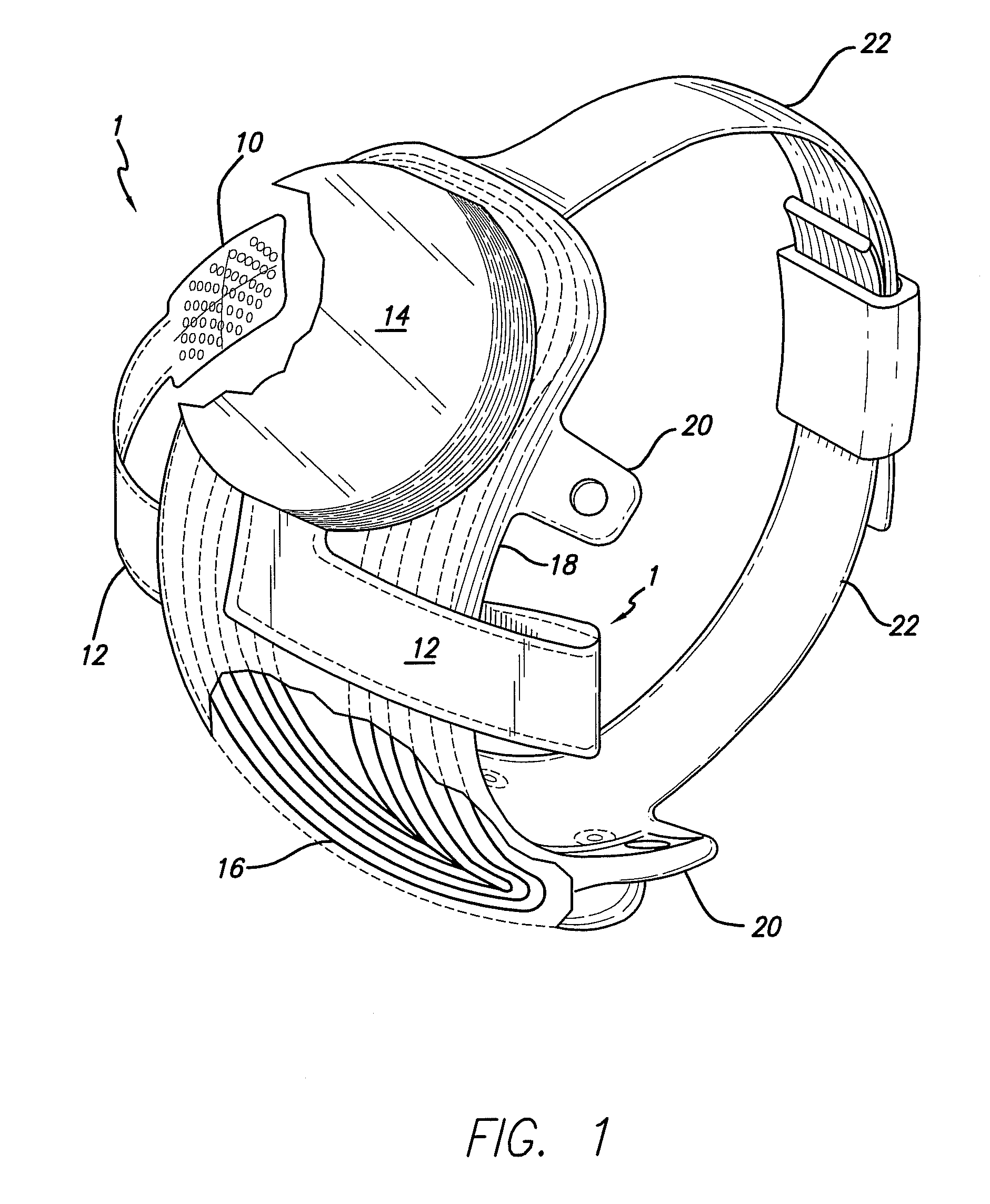
[0092]Polymer materials are useful as electrode array bodies for neural stimulation. They are particularly useful for retinal stimulation to create artificial vision, cochlear stimulation to create artificial hearing, or cortical stimulation for many purposes. Regardless of which polymer is used, the basic construction method is the same. A layer of polymer is laid down, commonly by some form of chemical vapor deposition, spinning, meniscus coating or casting. A layer of metal, preferably platinum, is applied to the polymer and patterned to create electrodes and leads for those electrodes. Patterning is commonly done by photolithographic methods. A second la...


PUM

PropertyMeasurementUnit
Flexibilityaaaaaaaaaa
Biocompatibilityaaaaaaaaaa

Abstract

A flexible circuit electrode array with more than one layer of metal traces comprising: a polymer base layer; more than one layer of metal traces, separated by polymer layers, deposited on said polymer base layer, including electrodes suitable to stimulate neural tissue; and a polymer top layer deposited on said polymer base layer and said metal traces. Polymer materials are useful as electrode array bodies for neural stimulation. They are particularly useful for retinal stimulation to create artificial vision, cochlear stimulation to create artificial hearing, or cortical stimulation many purposes. The pressure applied against the retina, or other neural tissue, by an electrode array is critical. Too little pressure causes increased electrical resistance, along with electric field dispersion. Too much pressure may block blood flow.

Description

CROSS-REFERENCE TO RELATED APPLICATIONS[0001]This Application claims the benefit of U.S. Provisional Application No. 60 / 856,455, “Flexible Circuit Electrode Array”, filed Nov. 2, 2006 and this application is a Continuation-In-Part of U.S. application Ser. No. 11 / 821,328, filed Jun. 21, 2006, which claims the benefit of U.S. Provisional Application No. 60 / 774,407, “Flexible Circuit Electrode Array and Method of Manufacturing the Same”, filed Feb. 17, 2006 and which claims the benefit of U.S. Provisional Application No. 60 / 815,311, “Flexible Circuit Electrode Array and Method of Manufacturing the Same”, filed Jun. 21, 2006 and which is a Continuation-In-Part of U.S. application Ser. No. 11 / 413,689, filed Apr. 28, 2006 and which is a Continuation-In-Part of U.S. application Ser. No. 11 / 207,644, filed Aug. 19, 2005 which claims the benefit of U.S. Provisional Application No. 60 / 676,008, “Thin Film Electrode Array”, filed Apr. 28, 2005, the disclosures of all are incorporated herein by r...

Claims


Application Information

Patent Timeline
IPC IPC(8): A61N1/05
CPCA61N1/0543A61N1/36046H05K1/118Y10T29/49156H05K3/388H05K3/4644Y10T29/49158H05K3/0014A61N1/0541H05K1/028H05K1/0353H05K1/09H05K1/111H05K1/115H05K3/0017H05K3/0041H05K3/06H05K3/188H05K3/22H05K2201/0129H05K2201/0133H05K2201/0141H05K2201/0154
Inventor NEYSMITH, JORDAN MATTHEWTALBOT, NEIL HAMILTONLITTLE, JAMES SINGLETONMECH, BRIAN V.GREENBERG, ROBERT J.YAO, QINGFANGZHOU, DAO MIN
Owner CORTIGENT INC
Why Eureka
Try Eureka