[0009]A “link-fuse” joint consistent with the present invention enables a
shear wall or steel
braced frame to withstand a seismic event without experiencing significant beam or joint failure. The link-fuse joint is also referred to as a joint connection herein. The link-fuse joint is generally utilized in a link beam
assembly. The link-fuse joint may be incorporated, for example, into the
reinforced concrete shear walls or steel braced frames of a building or other structure subject to seismic activity and improves the structure's dynamic characteristics by allowing the link-fuse joint to slip under extreme loads. This slippage changes the structure's dynamic characteristics by lengthening the structure's fundamental period and
softening the structure, which allows the structure to exhibit elastic properties during seismic events. By utilizing the link-fuse joint, it is generally not necessary to use shear walls or steel frames and link beams as large as typically used for a similar sized structure to withstand an extreme seismic event. Accordingly, overall building costs can also be reduced through the use of a link-fuse joint consistent with the present invention.
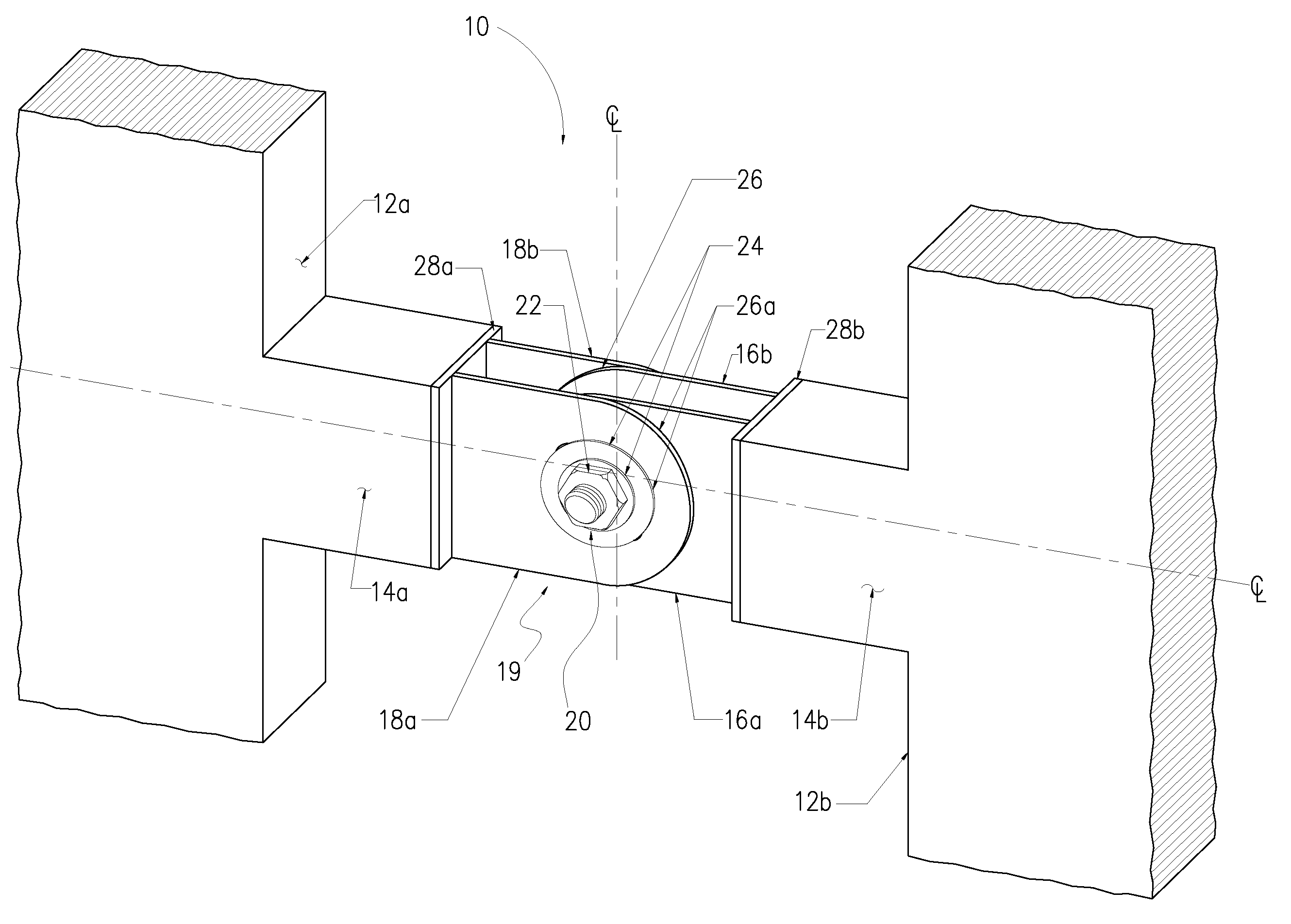
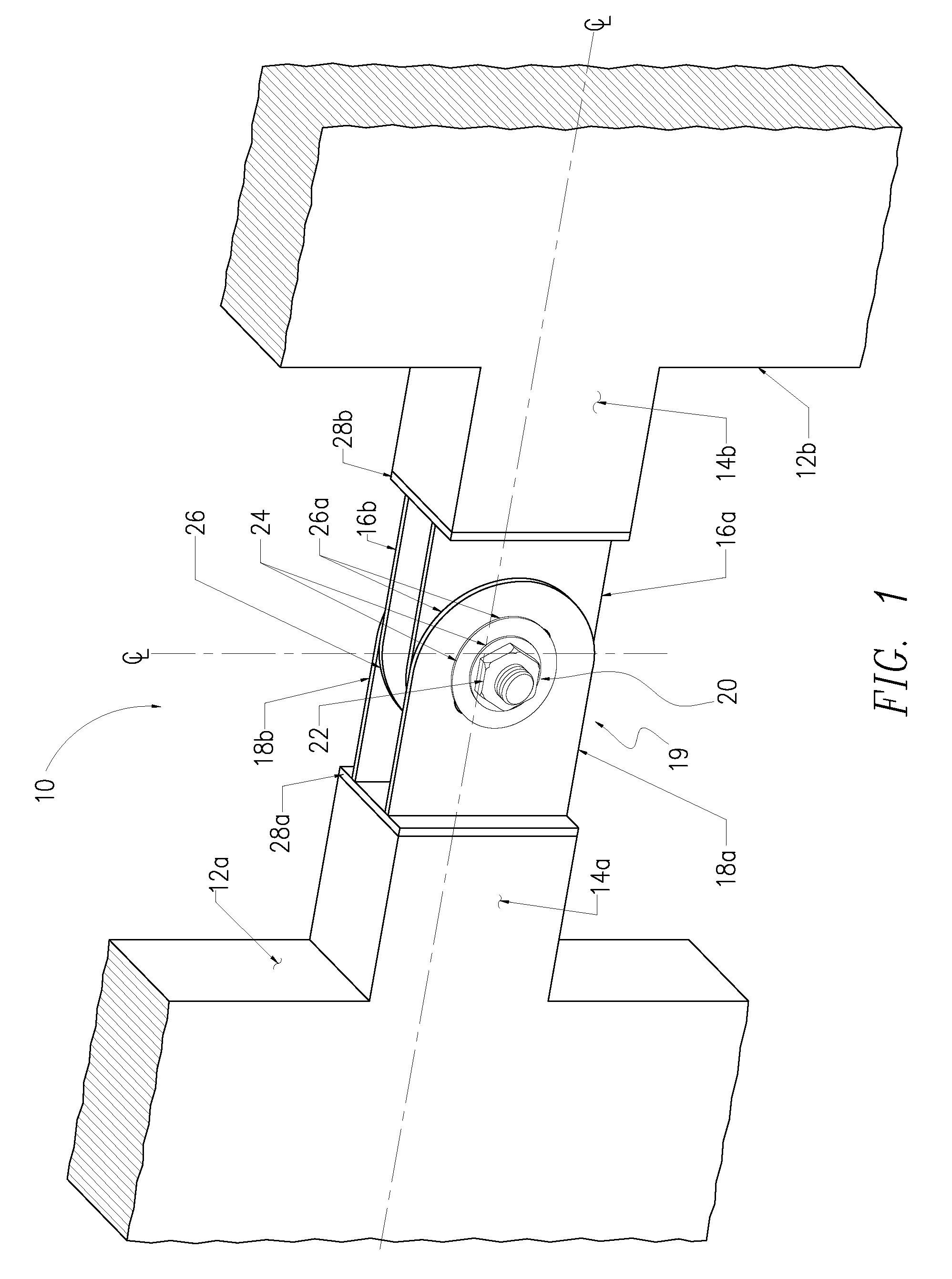
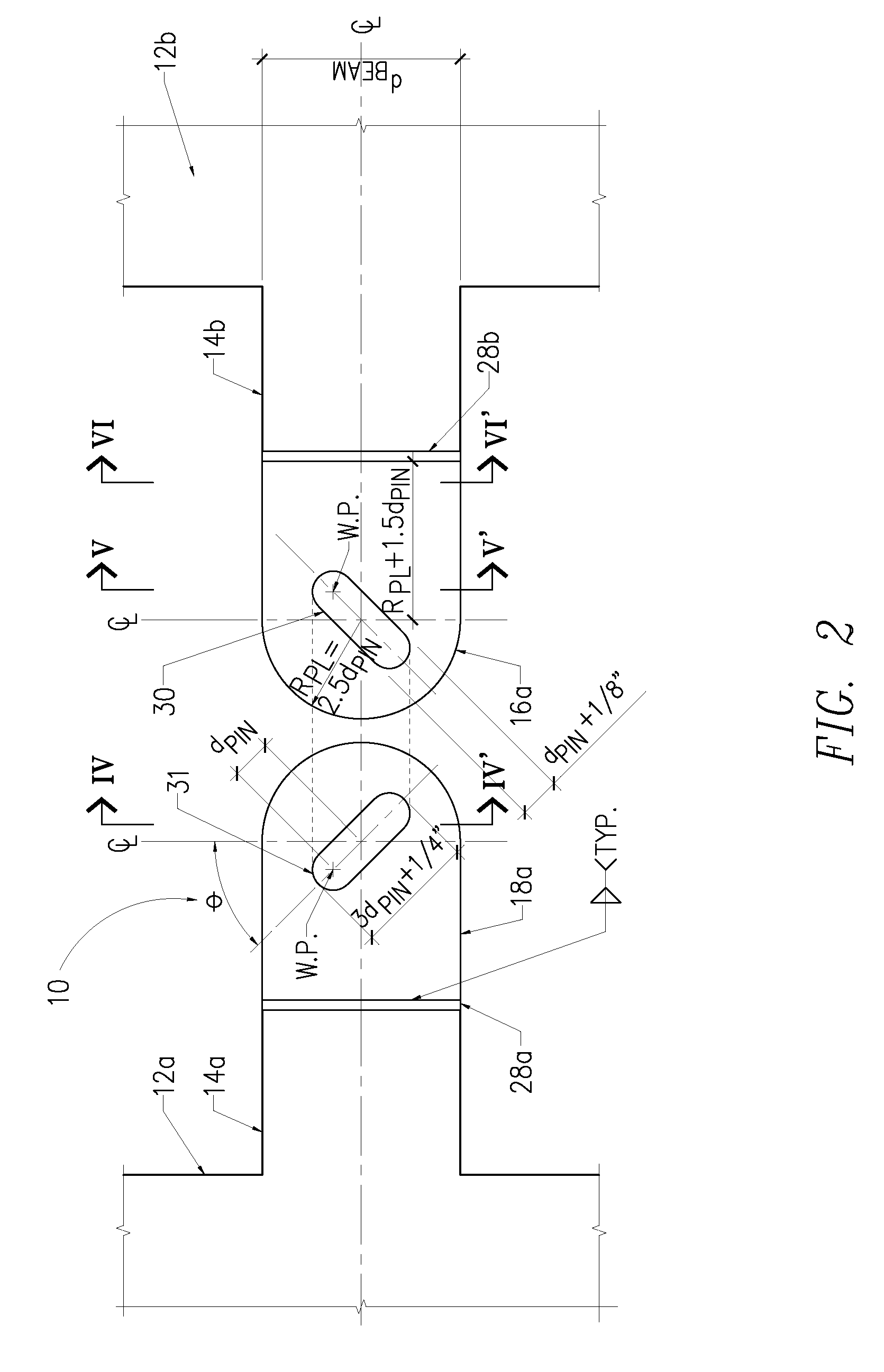
[0010]The link-fuse joint may be employed in a link beam, where the beam attaches to neighboring walls or frames of a structure. In the link-fuse joint, a plate assembly within a beam is designed to mate and be held together by a pin assembly extending through connection plates that extend outward from the plate assembly. Additionally, the plate assembly has diagonally opposed slots. The plate assembly may be secured together, for example, by a
threaded rod, multiple threaded rods, multiple high-strength steel bolts, and the like. These connections allow for the slotted plates to slip relative to each other when subject to extreme seismic loads without a significant loss in clamping force. Movement in the joint may be further restricted by treating the faying surfaces of the plate assembly with
brass. The
brass shims used within the connection possess a predetermined load-displacement behavior and excellent cyclic attributes.
[0011]The friction developed from the clamping force within the plate assembly with the
brass shims against the steel surface prevents the joint from slipping under most service loading conditions, such as those imposed by wind, gravity, and moderate seismic vents. The
threaded rod(s) or high-strength bolts are torqued to provide a slip resistant connection by developing friction between the connected surfaces. However, under extreme
seismic loading condition, the level of force applied to the connection exceeds the product of the
coefficient of friction times the normal rod or bolt clamping force, which causes the joint to slip in a planer direction while maintaining
connectivity.
[0012]The sliding of the joint during seismic events provides for the transfer of shear forces and
bending moment from the link beams to the shear walls or braced frames. This sliding dissipates energy, which is also known as “fusing.” This energy dissipation reduces potential damage to the structure due to seismic activity.
[0013]In accordance with devices consistent with the present invention, a joint connection is provided. The joint connection comprises a first plate assembly having a first connection plate including a first diagonal slot formed therethrough. A second plate assembly has a second connection plate including a second diagonal slot formed therethrough. The second diagonal slot is diagonally opposed to the first diagonal slot. The second connection plate is position such that at least a portion of the second diagonal slot aligns with a portion of the first diagonal slot. A pin is positioned through the first diagonal slot and the second diagonal slot. The joint connection accommodates a slippage of at least one of the first and second plate assemblies relative to each other when the joint connection is subject to a seismic load and without significant loss of clamping force.
[0014]Although a joint connection consistent with the present invention will slip under extreme seismic loads to dissipate the energy, the joints will, however, remain elastic due to their construction. Furthermore, the joint generally does not becomes plastic nor yields when subjected to the loading and the slip. This allows, for example, a
shear wall structure utilizing the joint connection to remain in service after enduring a seismic event and
resist further seismic activity.

